Micromechanical component

a micro-mechanical and component technology, applied in the direction of speed/acceleration/shock measurement, measurement devices, instruments, etc., can solve the problems of large problem, increased space requirement, unfavorable overload resistance, etc., and achieve high zero-point stability, negligible space requirement, and overload resistance high

Active Publication Date: 2010-05-20
ROBERT BOSCH GMBH
View PDF25 Cites 56 Cited by
  • Summary
  • Abstract
  • Description
  • Claims
  • Application Information

AI Technical Summary

Benefits of technology

[0017]According to the present invention, a method for manufacturing a micromechanical component for detecting an acceleration is also proposed. The method includes providing a substrate, forming an insulating layer on the substrate, forming a patterned conductive layer on the insulating layer having a first and a second electrode, forming a sacrificial layer on the conductive layer, and forming a patterned functional layer on the sacrificial layer for a rotatable flywheel mass in the form of a rocker having a first and a second lever arm. The first lever arm has a first hole structure having a number of first cut-outs, and the second lever arm has a second hole structure having a number of second cut-outs. Furthermo...

Problems solved by technology

Since the process-related surface potentials may change with the temperature or during the lifetime of component 100, for example, the tilting of the rocker may change and thus undesired offset signals may result.
Such effects pose a large problem in applications for detecting small acceleration values (low-g sensors) such as ESP (electronic stability program), for example, or starting assistance such as HHC (hill hold control).
Furthermore, supplementary mass 153 results in an increased space requirement ...

Method used


Image

  • Micromechanical component
  • Micromechanical component
  • Micromechanical component

Examples


Embodiment Construction

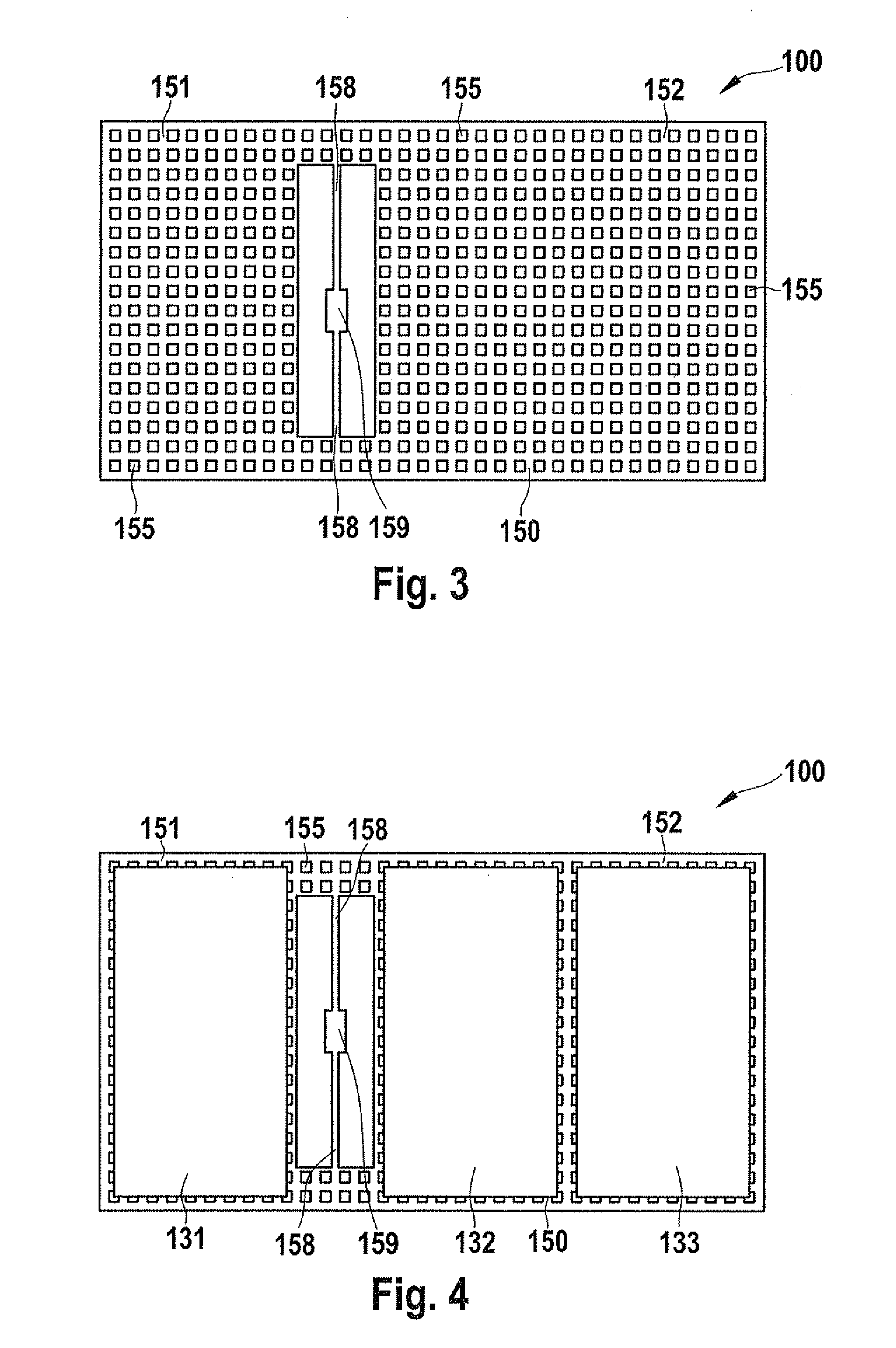
[0029]FIG. 5 shows a top-view illustration of a micromechanical component 200 according to one specific embodiment. Component 200 has a rotatable flywheel mass in the form of a rocker 250 having a first lever arm 251 and a second lever arm 252 whose outer dimensions are identical. A recess is provided between the two lever arms 251, 252, and two torsion bars 258 are disposed inside of it. Torsion bars 258 define an axis of rotation, around which rocker 250 may be rotated. Furthermore, torsion bars 258 are connected to a supporting element 259, via which rocker 250 is connected to an underlying conductive layer 230 of a substrate 210 (FIG. 9). Conductive layer 230 includes a first electrode 231 and second electrode 232 whose lateral position relative to lever arms 251, 252 becomes clear with the aid of FIG. 6. In this instance, first lever arm 251 is situated across from first electrode 231, and second lever arm 252 is situated across from second electrode 232, and they respectively ...


PUM


Abstract

A micromechanical component for detecting an acceleration. The component includes a conductive layer having a first and a second electrode and a rotatable flywheel mass in the form of a rocker having a first and a second lever arm. The first lever arm is situated opposite the first electrode, and the second lever arm is situated opposite the second electrode. The first lever arm has a first hole structure having a number of first cut-outs, and the second lever arm has a second hole structure having a number of second cut-outs. The first and the second lever arm have different masses. The component is characterized by the fact that the outer dimensions of the first and second lever arms correspond, and the first hole structure of the first lever arm differs from the second hole structure of the second lever arm. Furthermore, a method for manufacturing such a micromechanical component is provided.

Description

CROSS-REFERENCE[0001]This application claims the benefit under 35 U.S.C. §119 of German Patent Application No. DE 102008043788.3 filed on Nov. 17, 2008, which is expressly incorporated herein by reference in its entirety.FIELD OF THE INVENTION[0002]The present invention relates to a micromechanical component for detecting an acceleration using a rotatable flywheel mass in the form of a rocker. Furthermore, the present invention relates to a method for manufacturing such a component.BACKGROUND INFORMATION[0003]Micromechanical components, which are used in the automotive sector as acceleration sensors, for example, normally have a microstructure having a movable functional element. The microstructure, which is also called a MEMS structure (micro-electro-mechanical system), may include a rotatable flywheel mass in the form of a rocker, for example. Examples of such sensors are described in European Patent Nos. EP 0 244 581 A1 and EP 0 773 443 B1. The sensors may be read in a capacitive...

Claims


Application Information

Patent Timeline
IPC IPC(8): G01P15/125H01L21/30
CPCG01P15/125G01P15/0802G01P2015/0831
Inventor CLASSEN, JOHANNES
Owner ROBERT BOSCH GMBH
Why Eureka
Try Eureka