Electromagnetic flowmeter with variable excitation frequency

A technology of electromagnetic flowmeter and excitation frequency, which is applied in the application of electromagnetic flowmeter to detect fluid flow, volume/mass flow generated by electromagnetic effect, measurement device, etc. The effect of good zero-point stability

Active Publication Date: 2018-01-02
SHANGHAI UNIV
View PDF7 Cites 0 Cited by
  • Summary
  • Abstract
  • Description
  • Claims
  • Application Information

AI Technical Summary

Problems solved by technology

Therefore, the method of finding the optimal excitation frequency at each flow velocity point in the calibration state cannot reduce the various noises of the electromagnetic flowmeter in actual operation.
Because the variable excitation frequency method in the two patents does not involve the related technology of changing the excitation frequency according to the size of the noise

Method used


Image

  • Electromagnetic flowmeter with variable excitation frequency
  • Electromagnetic flowmeter with variable excitation frequency

Examples


Embodiment 1

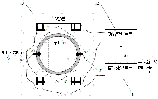
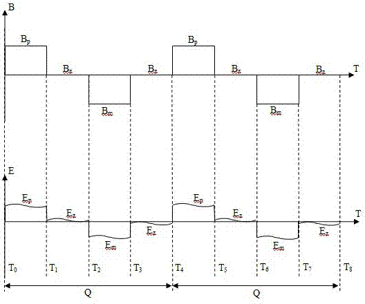
[0027] An electromagnetic flowmeter with variable excitation frequency, including a signal processing unit 1, an excitation drive unit 2, and a sensor 3 with a coefficient K0; it is characterized in that: the signal processing unit 1 is electrically connected to the excitation drive unit 2 and has The sensor 3 with coefficient K0, the excitation drive unit 2 is electrically connected with the sensor 3 with coefficient K0; the signal processing unit 1 outputs the sequence S to the excitation drive unit 2, so that the excitation drive unit 2 makes the sensor 3 Generate a magnetic field B with an excitation frequency F that changes in direction positive and negative; when the fluid with an average velocity V passes through the sensor 3, the sensor 3 outputs an induced potential signal E=K0×V×B; the induced potential signal E is input to the signal processing unit 1. The signal processing unit 1 allows the excitation drive unit 2 to make the excitation frequency F of the magnetic f...

Embodiment 2

[0030] This embodiment is basically the same as Embodiment 1, and the special features are as follows:

[0031] In the above-mentioned electromagnetic flowmeter with variable excitation frequency, for the slurry fluid, the signal processing unit 1 estimates the slurry concentration value X of the fluid according to the current excitation frequency F and the fluid flow velocity V value:

[0032] ,

[0033] Among them, F 0 It is the frequency value that is one step lower than the current excitation frequency F value among the M fixed frequency points, and K is the coefficient that needs to be corrected for different types of slurry fluids. Obviously, as the number of M fixed frequency points of the excitation frequency F increases, the signal processing unit 1 can estimate the slurry concentration value X of the fluid more carefully.

[0034] In the above-mentioned electromagnetic flowmeter with variable excitation frequency, the signal processing unit 1 outputs the time seq...


PUM


Abstract

The invention relates to an electromagnetic flowmeter with variable excitation frequency, which includes a signal processing unit, an excitation drive unit and a sensor with coefficient K0. The signal processing unit outputs the timing sequence S to the excitation drive unit, and the excitation drive unit generates a magnetic field B with an excitation frequency F that changes direction in positive and negative directions in the sensor; when the fluid with an average velocity V passes through the sensor, the sensor outputs an induced potential signal E=K0×V ×B; the induced potential signal E is input to the signal processing unit; the output sequence S of the signal processing unit allows the excitation drive unit to generate an excitation cycle Q in the sensor with positive magnetic field B=Bp, zero magnetic field B=Bz=0 and negative magnetic field B =Bm=-Bp three states of magnetic field B, the corresponding excitation cycle Q is the reciprocal of the excitation frequency F, so that the induced potential signal E input to the signal processing unit has a corresponding signal Ep=K0×V×Bp, signal Ez=K0 ×V×Bz and signal Em=K0×V×Bm three states.

Description

technical field [0001] The invention relates to an electromagnetic flowmeter with variable excitation frequency, in particular to an electromagnetic flowmeter which changes the excitation frequency according to the magnitude of the noise in the induced potential signal output by the sensor. technical background [0002] Electromagnetic flowmeter is a flow measuring instrument based on Faraday's law of electromagnetic induction. Typically, there is a sensor, an excitation drive unit, and a signal processing unit in an electromagnetic flowmeter. The excitation drive unit makes the sensor have a magnetic field B perpendicular to the flow direction of the fluid. When the fluid flows through the sensor at an average flow rate V, the sensor will output an induced potential signal E=K0×B×V, where K0 is a sensor coefficient. The induced potential signal E is input to the signal processing unit, and the signal processing unit estimates the average flow velocity V of the fluid by mea...

Claims


Application Information

Patent Timeline
Patent Type & Authority Patents(China)
IPC IPC(8): G01F1/58G01N15/02G01D21/02
Inventor 李斌陈洁李新伟张欣王高阳
Owner SHANGHAI UNIV
Why Eureka
Try Eureka