Lubrication apparatus of fuel pump driven by fuel pump drive cam

a technology of lubrication apparatus and fuel pump, which is applied in the direction of lubrication of auxiliaries, positive displacement liquid engines, piston pumps, etc., can solve the problems of high fuel consumption, difficult lubrication throughout the fuel pump, and large friction in the fuel pump, so as to improve durability and rotation performance of the fuel pump, and reduce noise. the effect o

Inactive Publication Date: 2011-12-06
HYUNDAI MOTOR CO LTD +1
View PDF12 Cites 2 Cited by
  • Summary
  • Abstract
  • Description
  • Claims
  • Application Information

AI Technical Summary

Benefits of technology

[0020]Various aspects of the present invention are directed to provide a lubrication apparatus of a fuel pump driven by a fuel pump drive cam having advantages of improving durability and rotation performance of the fuel pump, and thereby reducing noise generated by friction therebetween, in which it directly lubricates a contact surface of the fuel pump drive cam and a tappet roller.

Problems solved by technology

Due to a high compression ratio of the GDI engine, a high compression ratio that is capable of exceeding a limit of a usual gasoline engine results in maximization of fuel consumption.
A great deal of friction occurs in the fuel pump due to the high pressure of the fuel.
Such a method has a merit of simplifying the structure, but it is difficult to lubricate throughout the fuel pump, and it is difficult to lubricate it at a slanted surface.
However, the method mentioned above has a drawback in that it is capable of lubricating only a specific part that is provided with an oil hole, and it is impossible to form a hole at a portion of the cam contacting the tappet of the fuel pump.
In addition, the cam rotates in such a state in which it rotatably contacts the roller mounted at the bottom of the cam so as to operate the tappet upwardly and downwardly, and the conventional tappet lubrication structure of the engine guides the tappet upwardly and downwardly by the roller between the tappet and the cam, but contact surfaces between the tappet and the fuel pump adaptor and between the cam and the roller are not lubricated smoothly thereby inducing abrasion, and consequently durability and rotation thereof are deteriorated.
Therefore, due to the abrasion occurring at the roller interposed between the cam and the roller tappet, durability thereof is deteriorated and thereby manufacturing cost is increased, and noise occurs at the contact portion thereof.

Method used


Image

  • Lubrication apparatus of fuel pump driven by fuel pump drive cam
  • Lubrication apparatus of fuel pump driven by fuel pump drive cam
  • Lubrication apparatus of fuel pump driven by fuel pump drive cam

Examples


Embodiment Construction

[0034]Reference will now be made in detail to various embodiments of the present invention(s), examples of which are illustrated in the accompanying drawings and described below. While the invention(s) will be described in conjunction with exemplary embodiments, it will be understood that present description is not intended to limit the invention(s) to those exemplary embodiments. On the contrary, the invention(s) is / are intended to cover not only the exemplary embodiments, but also various alternatives, modifications, equivalents and other embodiments, which may be included within the spirit and scope of the invention as defined by the appended claims.

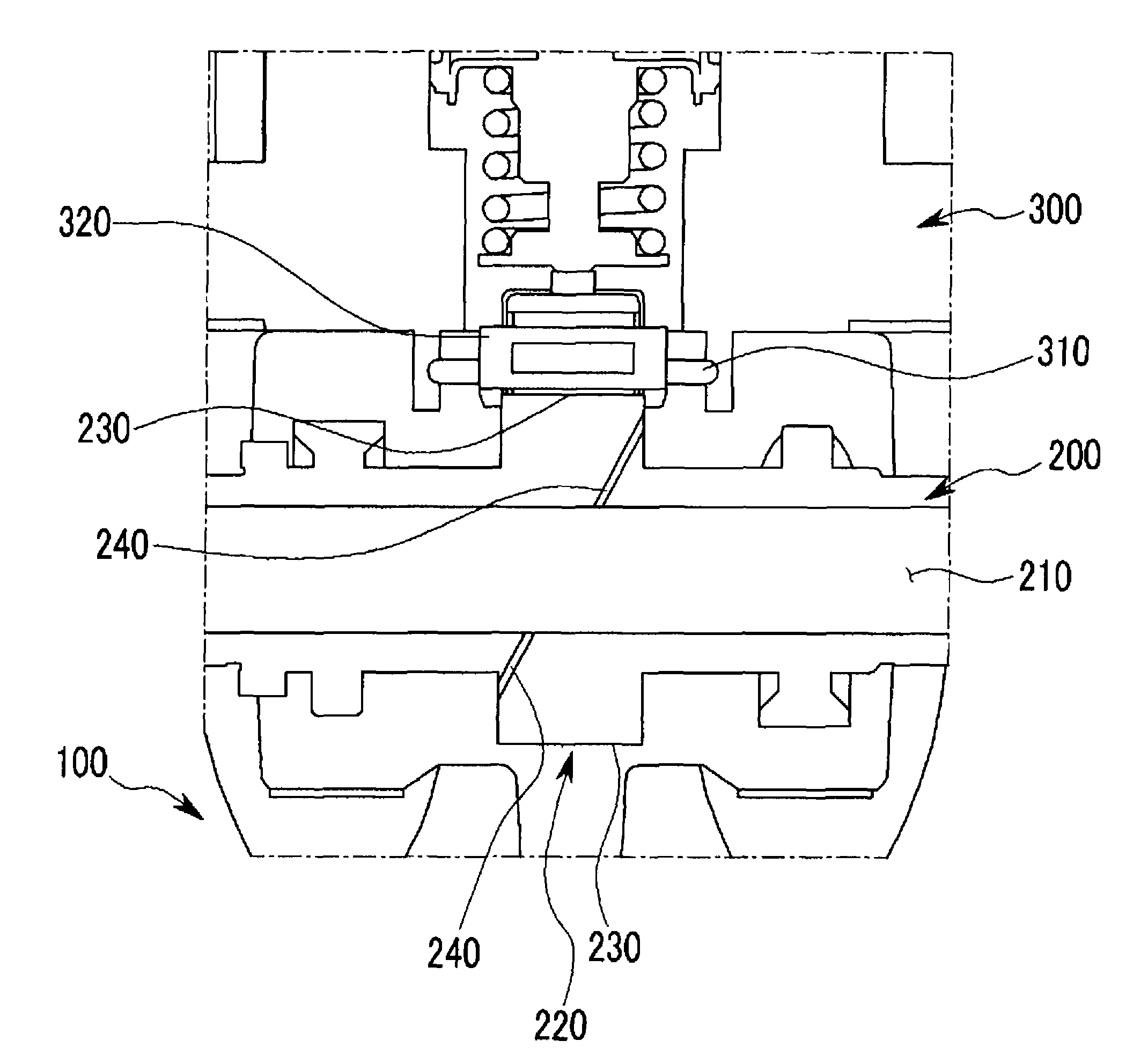
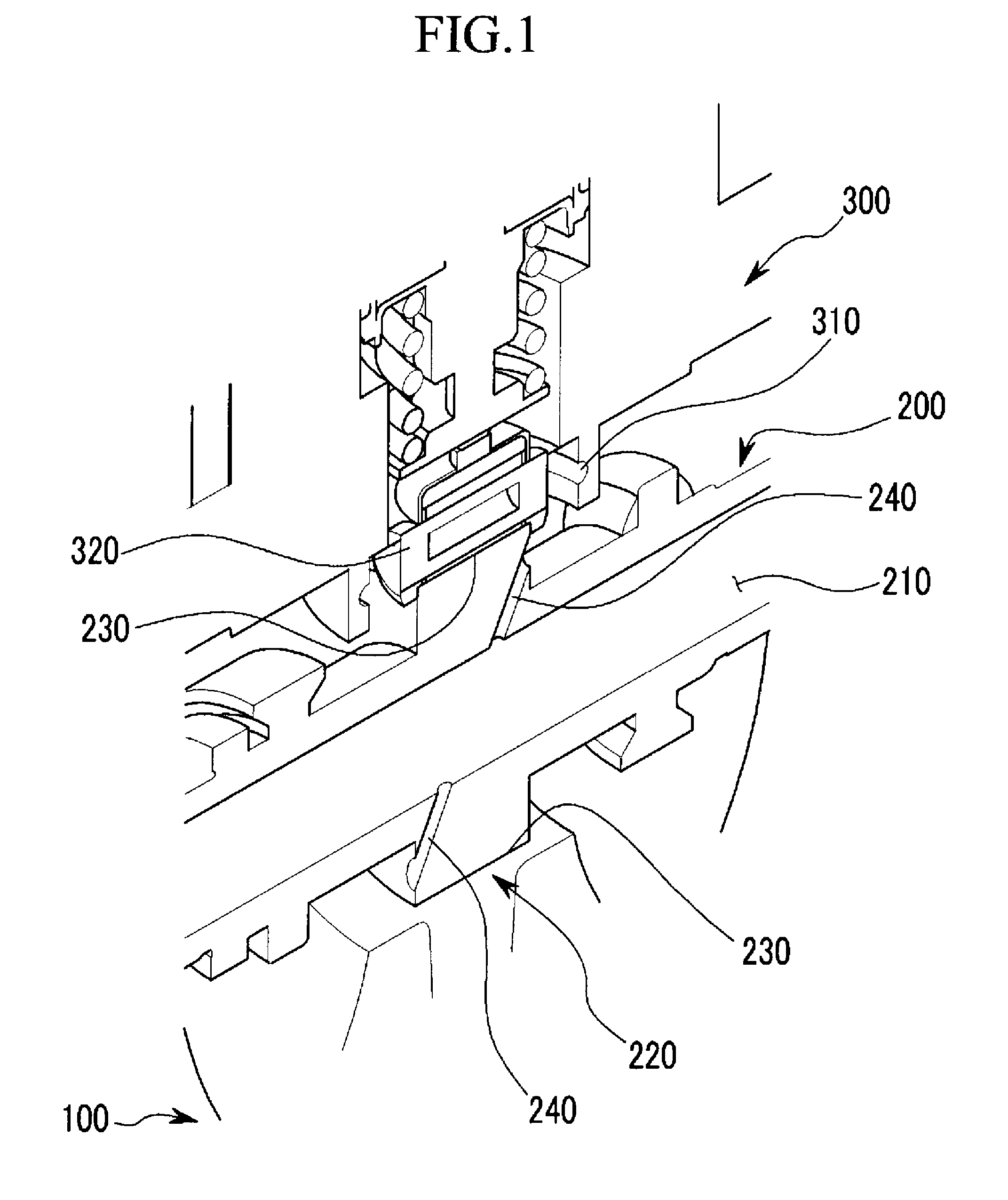
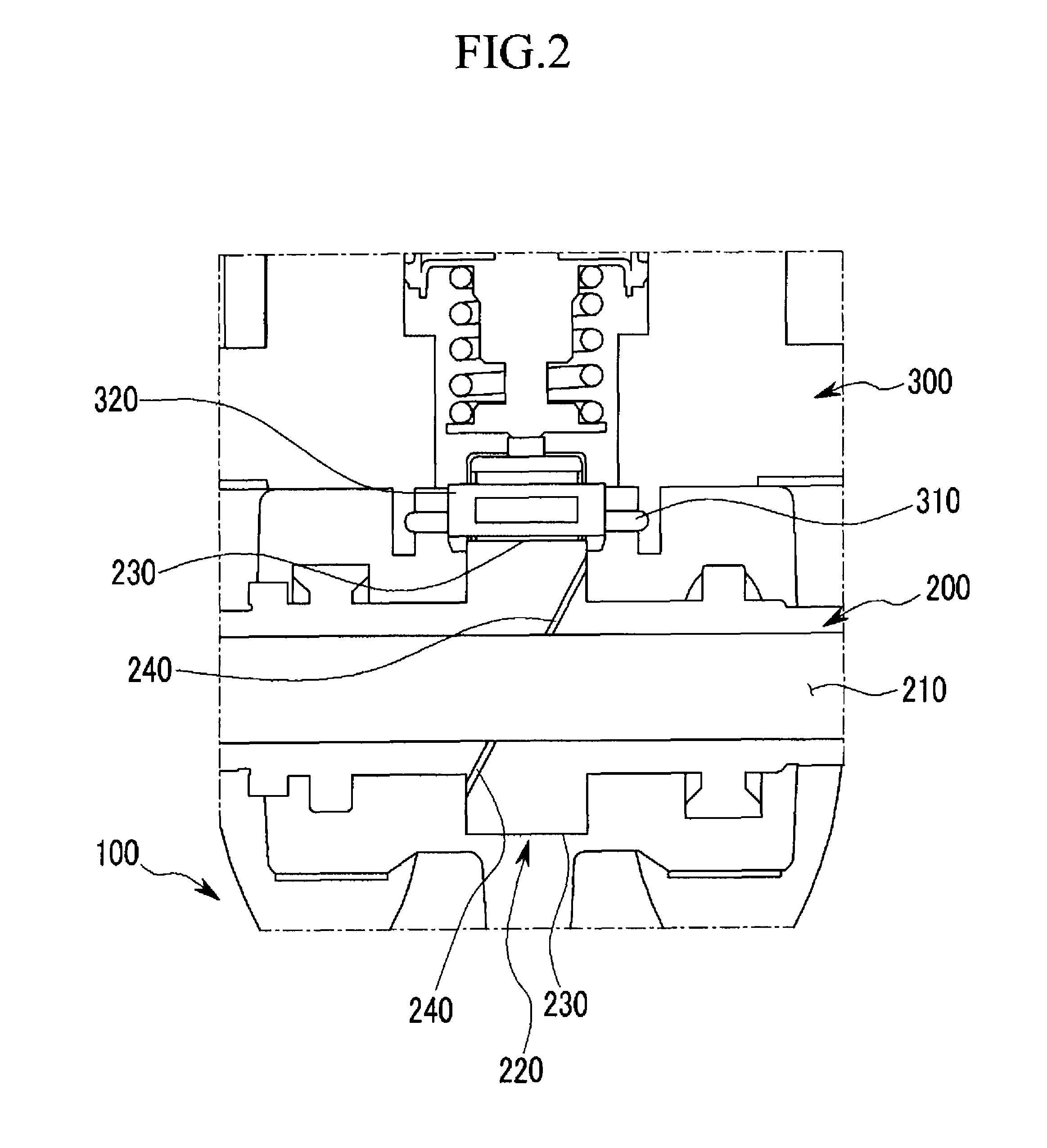
[0035]FIG. 1 is a perspective view showing a main portion of a lubrication apparatus of a fuel pump driven by a fuel pump drive cam according to an exemplary embodiment of the present invention, and FIG. 2 is a cross-sectional view showing a lubrication apparatus of a fuel pump driven by a fuel pump drive cam according to an exemplary...


PUM


Abstract

A lubrication apparatus of a fuel pump driven by a fuel pump drive cam, which lubricates a tappet moving reciprocally at an interior circumference of a fuel pump adaptor and the fuel pump operating the tappet, may include a cylinder head provided with a camshaft, an oil supplying passage formed in the camshaft as a hollow type so as to take oil to the interior of the camshaft, at least an oil branch passage formed to a cam lobe of the fuel pump drive cam so as to be communicated with the oil supplying passage, and a circular groove formed at the interior circumference of the fuel pump adaptor and corresponding to an injection direction of the oil supplied from the at least an oil branch passage.

Description

CROSS-REFERENCE TO RELATED APPLICATION[0001]The present application claims priority to Korean Patent Application No. 10-2008-0117558 filed on Nov. 25, 2008, the entire contents of which are incorporated herein for all purposes by this reference.BACKGROUND OF THE INVENTION[0002]1. Field of the Invention[0003]This present invention relates to a lubrication structure of an engine, and more particularly to a fuel pump lubrication device that is capable of effectively lubricating a tappet of the engine, a tappet roller, and a cam.[0004]2. Description of Related Art[0005]Technologies for a gasoline direct injection (GDI) engine have been studied in order to improve fuel consumption and performance of the engine.[0006]The GDI engine technologies are methods in which only air is drawn into the combustion chamber and is compressed and then fuel is injected therein, while in the case of a conventional gasoline engine, power is generated in a period of an intake stroke, a compression stroke, a...

Claims


Application Information

Patent Timeline
Patent Type & Authority Patents(United States)
IPC IPC(8): F01M1/02F01M1/06
CPCF02M59/102F02M59/44F04B9/042F04B53/18F01M1/06F01M1/02F02M37/04
Inventor LEE, SEUNG WOO
Owner HYUNDAI MOTOR CO LTD
Why Eureka
Try Eureka