Optical microscope apparatus

a microscope and optical technology, applied in the field of optical microscope equipment, can solve the problems of increased cost, dust generated by friction, and inability to prevent the generation of friction between the door and the motorized stage, and achieve the effect of maintaining the specimen environment at low cos

Inactive Publication Date: 2011-02-08
EVIDENT CORP
View PDF17 Cites 2 Cited by
  • Summary
  • Abstract
  • Description
  • Claims
  • Application Information

AI Technical Summary

Benefits of technology

[0007]With a method such as that described in Patent Document 1, in which a door is opened by pushing a motorized stage against the door, the apparatus may be produced at relatively low cost. However, generation of friction between the door and the motorized stage cannot be prevented. Consequently, there is a problem in that dust caused by the friction is generated upon repeated opening and closing.

Problems solved by technology

However, generation of friction between the door and the motorized stage cannot be prevented.
Consequently, there is a problem in that dust caused by the friction is generated upon repeated opening and closing.
However, this approach suffers from the problem of increased costs.
Therefore, there are disadvantages in that a long translation guide is required, production costs increase, and the size of the apparatus increases.
However, adjustment for increasing this accuracy becomes difficult and the time required for adjustment increases if the translation guide is long.
Moreover, there is a possibility that assembly costs may increase.

Method used


Image

  • Optical microscope apparatus
  • Optical microscope apparatus
  • Optical microscope apparatus

Examples


first embodiment

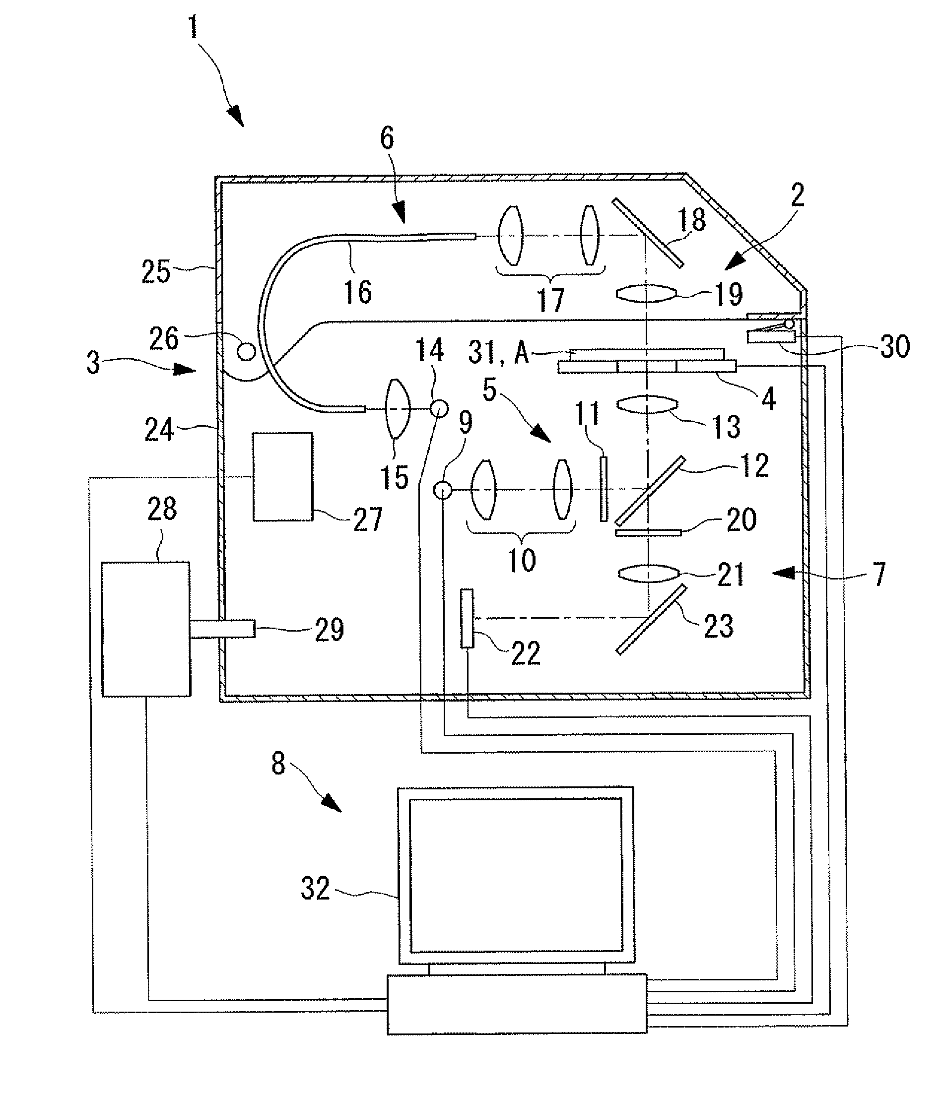
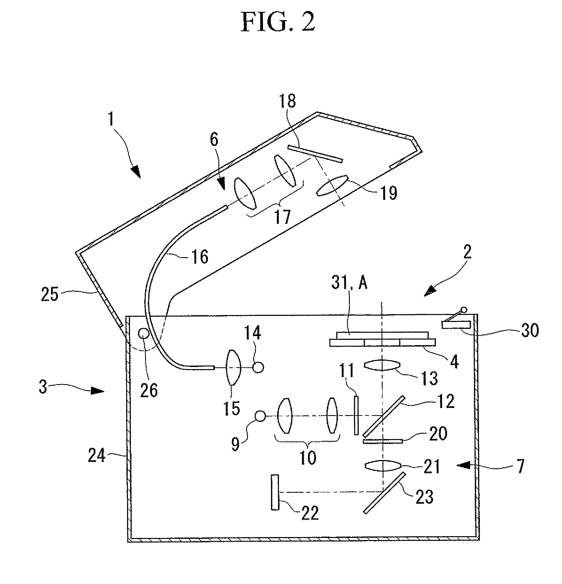
[0079]An optical microscope apparatus 1 according to a first embodiment of the present invention will be described below with reference to FIGS. 1 to 3.

[0080]As shown in FIG. 1, the optical microscope apparatus 1 according to the first embodiment includes an inverted microscope 2 and a housing 3 that contains the inverted microscope 2.

[0081]The inverted microscope 2 includes a motorized stage 4 on which a specimen A is fixed using a clamping mechanism (not shown); an epi-illumination optical system 5 that is disposed below the motorized stage 4 and that irradiates the specimen A placed on the motorized stage 4 with excitation light vertically from below; a transmission-illumination optical system 6 that is disposed above the motorized stage 4 and that irradiates the specimen A with white light vertically from above; a detection optical system (image-forming optical system) 7 that detects fluorescence and transmitted light emitted downward from the specimen A; and a control unit 8.

[0...

second embodiment

[0106]Next, an optical microscope apparatus 40 according to a second embodiment of the present invention will be described with reference to FIGS. 12 to 14.

[0107]In the description of the second embodiment, parts that are the same as those in the above-described optical microscope apparatus 1 according to the first embodiment will be indicated by the same reference numerals.

[0108]The structure of a housing 41 of the optical microscope apparatus 40 according to the second embodiment differs from the first embodiment. However, the inverted microscope 2 provided inside has exactly the same structure.

[0109]The housing 41 of the optical microscope apparatus 40 according to the second embodiment includes a movable housing 44 that is movable in the horizontal direction by translation guides 43 and that is provided on a fixed housing 42, which is disposed on the lower side. A clicking mechanism (not shown) is interposed between the fixed housing 42 and the movable housing 44 so that the mov...

third embodiment

[0115]Next, an optical microscope apparatus 50 according to a third embodiment of the present invention will be described with reference to FIGS. 15 to 19.

[0116]In the description of the third embodiment, parts that are the same as those in the above-described optical microscope apparatus 1 according to the first embodiment or the optical microscope apparatus 40 according to the second embodiment will be indicated by the same reference numerals.

[0117]An optical microscope apparatus 50 according to the third embodiment includes an inverted microscope 51 and a housing 52 that contains the inverted microscope 51. Similar to the optical microscope apparatus 40 according to the second embodiment, the housing 52 opens and closes by sliding a movable housing 54 in the horizontal direction relative to a fixed housing 53.

[0118]The inverted microscope 51 includes a motorized stage 4 on which a specimen A is placed; an epi-illumination optical system 55 that is disposed above the motorized sta...


PUM


Abstract

The size and production costs of an optical microscope apparatus capable of blocking light or maintaining the specimen environment are reduced. The provided optical microscope apparatus includes a microscope that has a stage for mounting a specimen (A), a transmission-illumination optical system, and a detection optical system; and a housing that surrounds the microscope, wherein the housing includes a fixed housing, and a movable housing, wherein, among optical parts constituting the transmission-illumination optical system and the image-forming optical system, at least some optical parts disposed above the stage are movable, and wherein a switching mechanism is provided, the switching mechanism being configured to retract the optical parts away from above the stage when the movable housing is disposed in an open position relative to the fixed housing and to substantially align the optical axes of both optical systems when the movable housing is disposed in a closed position relative to the fixed housing.

Description

TECHNICAL FIELD[0001]The present invention relates to an optical microscope apparatus mainly for examining biological specimens, such as cells, and includes a housing for blocking light or maintaining the specimen environment.BACKGROUND ART[0002]Optical microscopes are generally used as means for examining living biological cells, such as a cultured cell specimens cultured in a culture medium on a petri dish or a microplate. Recently, optical microscopes include highly sensitive image-acquisition parts, such as cooled CCD cameras, so as to detect weak fluorescence from a fluorescently-labeled cultured cell and record it as image data. Since the fluorescence from a fluorescently-labeled cultured cell is extremely weak, it is necessary to prevent, as much as possible, light other than fluorescence from the cell, i.e., ambient light, from being detected in order to accurately detect the weak fluorescence. Therefore, some of the commercially available optical microscope apparatuses have...

Claims


Application Information

Patent Timeline
Patent Type & Authority Patents(United States)
IPC IPC(8): G02B21/00
CPCG02B21/088G02B21/16
Inventor SHIMADA, YOSHIHIRO
Owner EVIDENT CORP
Why Eureka
Try Eureka