Ball pin and ball joint

a technology of ball joints and ball pins, which is applied in the direction of couplings, mechanical equipment, rotary machine parts, etc., can solve the problems of premature wear or failure of the joint, corresponding disadvantageous consequences of joint wear, and the tribological system of the joint is particularly severe, so as to reduce corrosion protection, reduce wear and tear, and improve the effect of fatigue strength

Active Publication Date: 2013-03-21
ZF FRIEDRICHSHAFEN AG
View PDF10 Cites 3 Cited by
  • Summary
  • Abstract
  • Description
  • Claims
  • Application Information

AI Technical Summary

Benefits of technology

[0008]Against that background the purpose of the present invention is to provide a ball pin and a ball joint which has a high fatigue strength, good resistance to wear and thus long life, in particular under operating conditions with static pre-loading and micro-movements, or under high operating loads. Reduced corrosion protection in some areas of the ball pin, for example in the sealed area, is acceptable in favor of wear protection or compensated by other technical means such as an additional, corrosion-protected slide-ring. In particular, however, the previous mutual exclusion between surface layer hardening on the one hand and nitriding / oxidation on the other hand, that exists in the prior art, should be overcome so as, really for the first time, to achieve improved wear protection even with pins having a hardened surface layer.

Problems solved by technology

In the case of load-bearing joints subjected to static loading, for example in the chassis area of a motor vehicle, in certain situations (such as periods of rest in combination with only minimal joint movements, or freeway driving) the tribological system of the joint is particularly severely loaded, and in some circumstances this can result in premature wear or failure of the joint.
Because of this the mixed friction, that always exists in a ball joint, namely between fluid friction and solid-on-solid friction, is displaced more markedly toward solid-on-solid friction, with corresponding disadvantageous consequences for the wear of the joint.
Another problem known to affect ball joints is corrosion, particularly in the area of the ball pin sealed by sealing bellows, and—if moisture penetrates into the ball joint—also in the bearing gap between the joint ball and the ball socket.
This too increases the wear of the joint and can result in the onset of joint play and in the ultimately failure of the joint.
The problem is that in relation to high fatigue strength or load-bearing and wear resistance as well, the desired surface layer hardening of the ball pin should typically take place in the same surface areas of the pin which should also be protected by the nitriding treatment, namely primarily in the area of the joint ball and if necessary in the sealing bellows sealed area of the ball pin.
In summary therefore, the problem is that on the one hand the nitriding of the ball pin desired with a view to corrosion protection, and on the other hand the surface layer hardening desired with a view to long life and good wear resistance, have until now been mutually exclusive for a ball pin—at any rate so far as was known from the prior art.

Method used


Image

  • Ball pin and ball joint
  • Ball pin and ball joint

Examples


Embodiment Construction

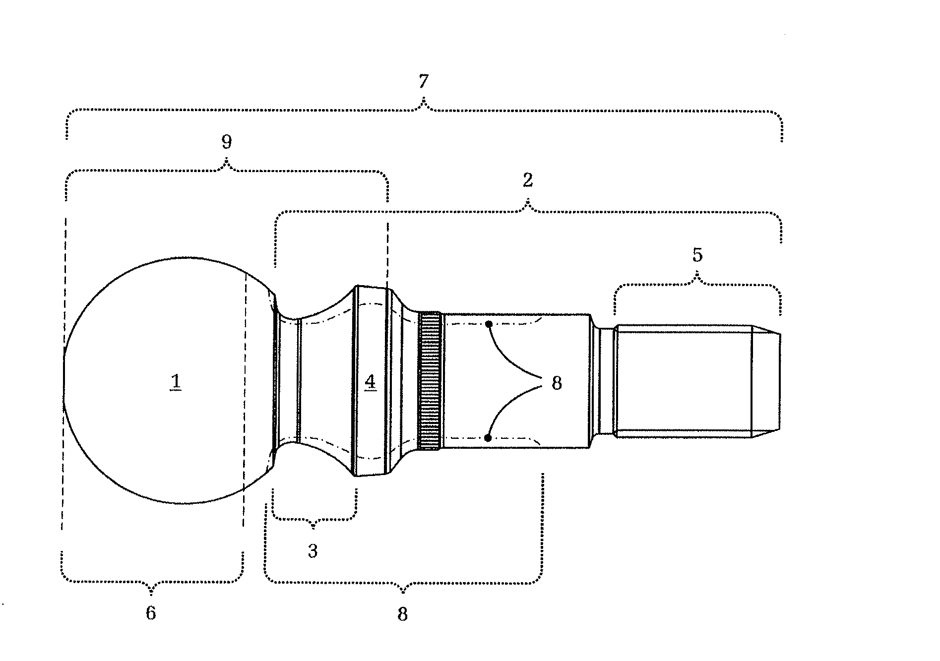
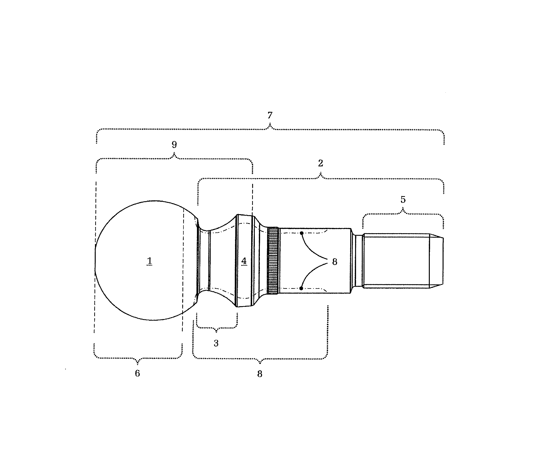
[0025]The FIGURE shows the ball pin, which comprises a joint ball 1, a shaft area 2, a neck area 3, a seal area 4 (against which a sealing bellows rests) and a threaded area 5.

[0026]In this case the example embodiment of a ball pin has an oxide layer over its entire length or surface 7. On the one hand the oxide layer leads to an improvement of the corrosion protection, while on the other hand—in accordance with the applicant's new insight—in particular it improves the wear resistance in the bearing contact area 6 between the joint ball 1 and the ball socket (not shown) of the ball joint. Thus, the ball pin shown is particularly suitable for use under high static pre-loading and / or during periods of operation with micro-movements, in which solid-on-solid friction between the ball pin and the ball socket predominates.

[0027]In this case the ball pin shown is additionally provided with surface layer hardening in the area 8 (also indicated with dot-dash lines). This is the area in which...


PUM


Abstract

A ball joint with a ball pin and a steel ball pin with a joint ball. The ball joint and ball pin are suitable for use when solid-on-solid friction predominates, for example under high static pre-loading or under high operational loads and with small joint movements. At least in a bearing contact area, between the joint ball and the bearing shell, does not include any nitrided layer. The surface of the ball pin has an oxide layer, provided as wear protection, at least in the bearing contact area of the joint ball. The oxide layer in the ball joints, previously regarded (as part of the nitriding treatment) as only improving corrosion protection functions as a form of wear protection. Thus, the mutual exclusion between increasing the fatigue strength (by surface layer hardening) and improving the wear resistance (by nitriding/oxidation) is overcome with such ball pins.

Description

[0001]This application claims priority from German patent application serial no. 10 2011 082 921.0 filed Sep. 19, 2011.FIELD OF THE INVENTION[0002]The invention concerns a ball pin made of steel and a ball joint.BACKGROUND OF THE INVENTION[0003]In the case of load-bearing joints subjected to static loading, for example in the chassis area of a motor vehicle, in certain situations (such as periods of rest in combination with only minimal joint movements, or freeway driving) the tribological system of the joint is particularly severely loaded, and in some circumstances this can result in premature wear or failure of the joint. This is related to the fact that in these situations lubricant present in the ball joint is partially expressed out of the contact area between the ball pin and the bearing shell due to the high load in combination with at most small movements of the joint. Because of this the mixed friction, that always exists in a ball joint, namely between fluid friction and ...

Claims


Application Information

Patent Timeline
Patent Type & Authority Applications(United States)
IPC IPC(8): F16C11/06
CPCF16C11/0604F16C2223/10Y10T403/32631
Inventor PAPE, KLAUS
Owner ZF FRIEDRICHSHAFEN AG
Why Eureka
Try Eureka