Detachable light emitting device using light emitting diode modules

Inactive Publication Date: 2013-04-04
OH WAN HO
View PDF0 Cites 23 Cited by
  • Summary
  • Abstract
  • Description
  • Claims
  • Application Information

AI Technical Summary

Benefits of technology

[0010]According to the embodiments of the present invention, because the detachable light emitting device using light emitting diode modules includes radiation stands vertically erected respectively on both left and right sides of inside the body casing to be assembled, light guide plate stand and LED module mounting stand sequentially and vertically inserted into and coupled in the inside of the radiation stand, a LED module vertically inserted to be coupled to the LED module mounting stand to be simply and stably mounted on the LED module mounting stand, and a light guide plate closely contacting the LED module disposed to be adjacent to the light guide plate, light-emitting efficiency can be enhanced. Also, because the detachable light emitting device using light emitting diode modules includes a LED module mounting stand, a light guide plate stand and the r

Problems solved by technology

However, because the light emitting means includes a plurality of light emitting diodes closely disposed in the printed circuit board, the light emitting means has large power consumption, and thus, a cost of manufacturing and maintaining the light emitting means increases.
Also, because of high heat occurring in the diodes, a life of the light emitting diode is shortened, and thus, a malfunction occurs frequently.
Moreover, the light emitting means displays letters or figures using a type of dot emitting when the light emitting diodes are being closely disposed in the printed circuit board, and thus, when the light emitting means is applied to a traffic light, light emitted from diodes directly irradiates and blinds a driver to cause a car accident.
Therefore, an installing work is very difficult and needs many times. Also, when the LED module is attached to the light guide plate with the aluminum tape or the like, many cases where the side surface of the light guide plate does not exactly face the LED module, and is

Method used


Image

  • Detachable light emitting device using light emitting diode modules
  • Detachable light emitting device using light emitting diode modules
  • Detachable light emitting device using light emitting diode modules

Examples


Example

[0021]Reference will now be made in detail to the exemplary embodiments of the present invention, examples of which are illustrated in the accompanying drawings. Wherever possible, the same reference numbers will be used throughout the drawings to refer to the same or like parts. Hereinafter, embodiments of the present invention will be described in detail with reference to the accompanying drawings.

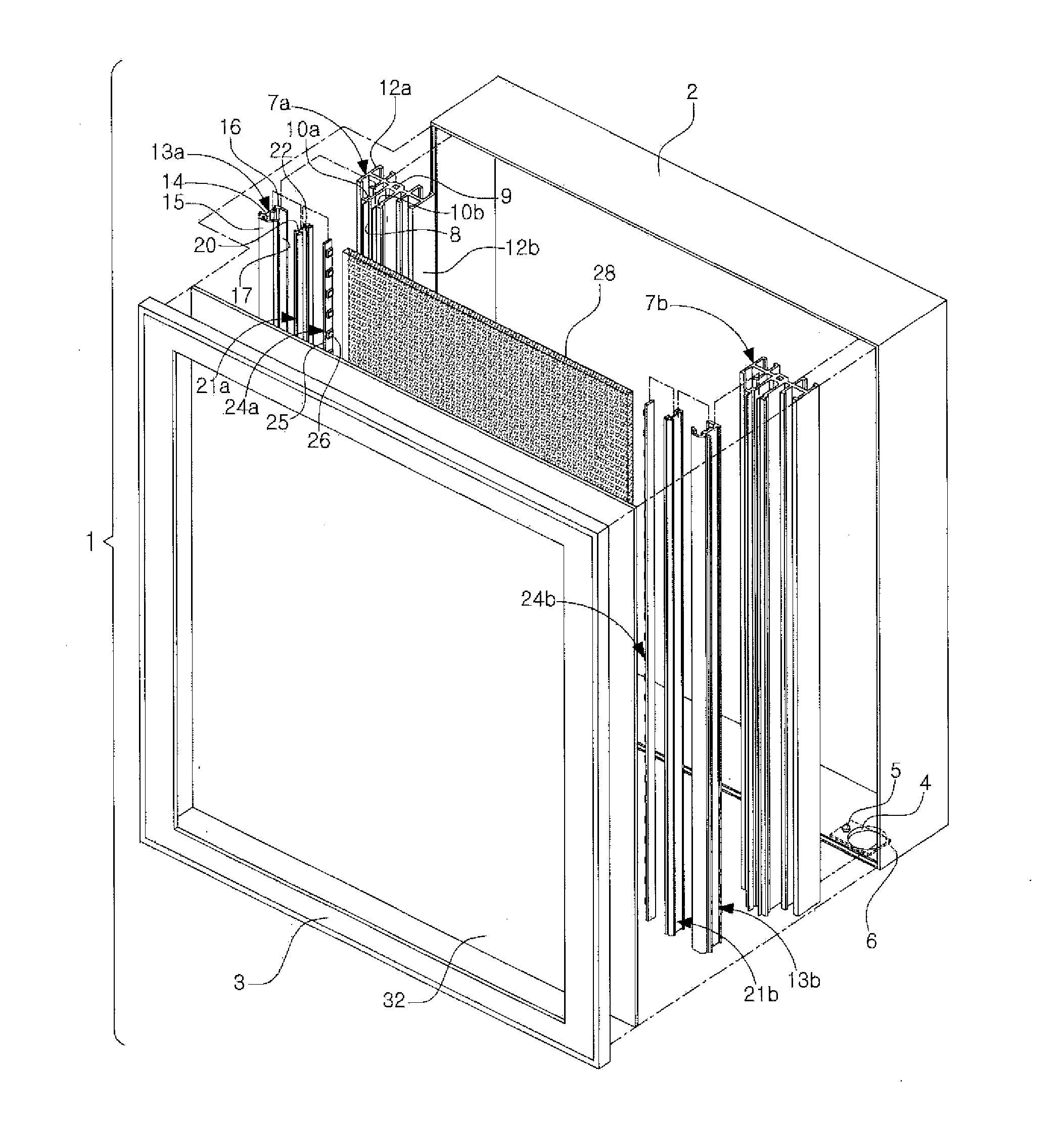
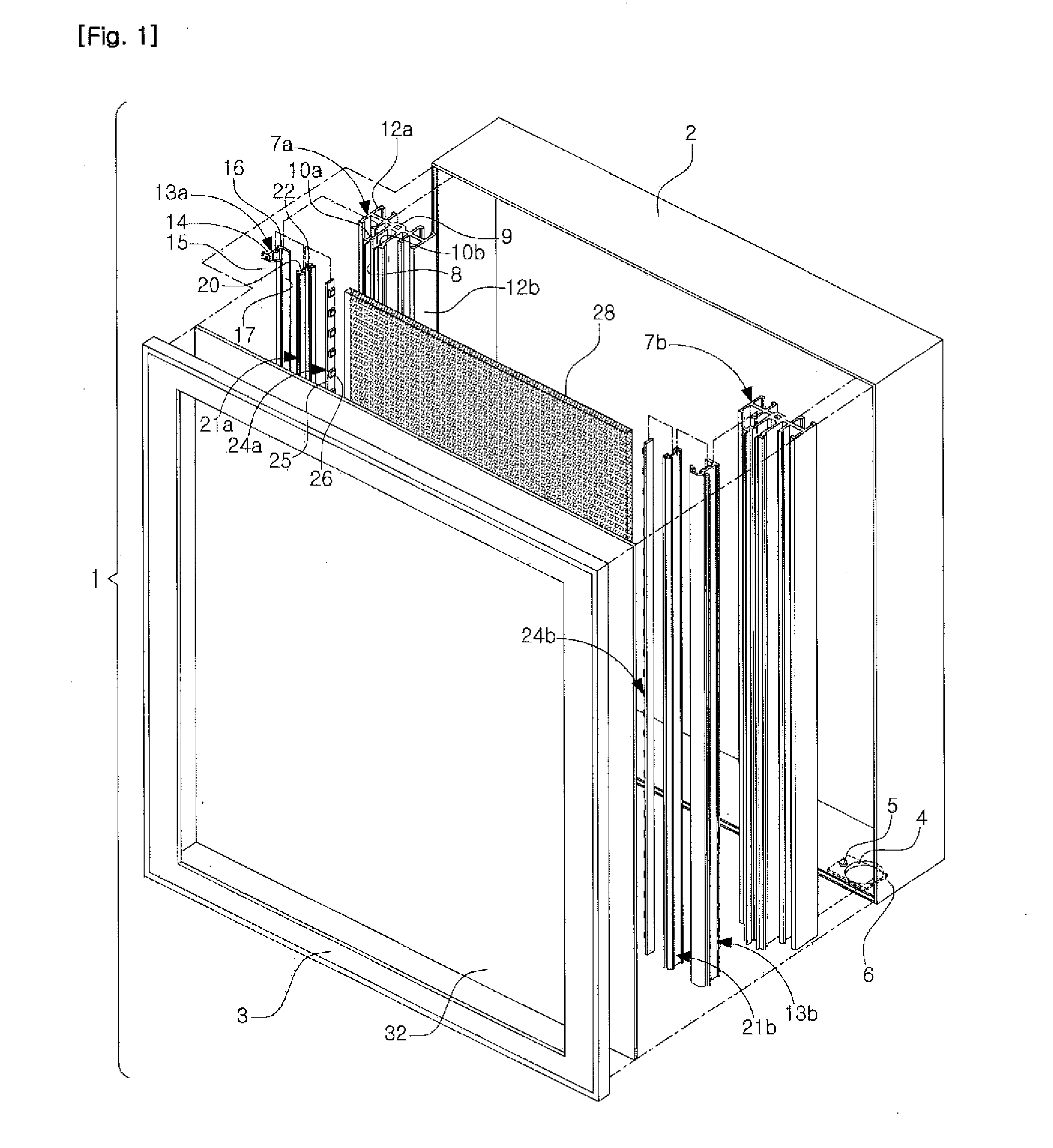
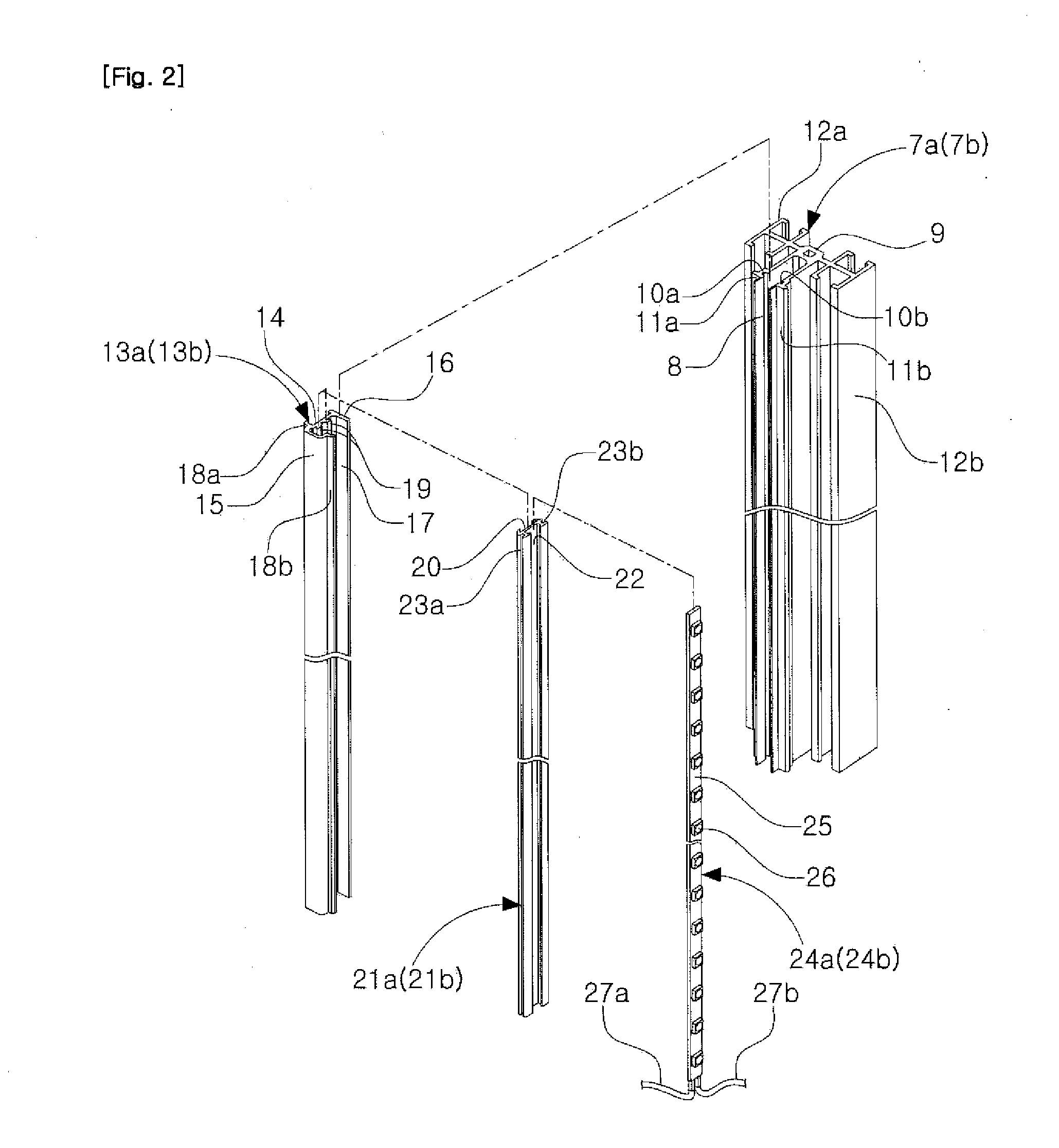
[0022]The detachable light emitting device 1 using light emitting diode modules according to the present invention, as shown in FIGS. 1 to 9, includes a light guide plate 28 outputting plane light so as to increase light-emitting efficiency, and a LED modules 24a and 24b each of which is formed in a bar shape, and inserted and coupled to be assembled in one side surface or both side surface of the light guide plate 28 when the LED modules are being closely contacting the light guide plate 28, and thus, each of the LED modules 24a and 24b can be easily attached or detached, whereupon a re...


PUM


Abstract

The present invention relates to a detachable light emitting device using light emitting diode modules, and the detachable light emitting device comprises: a body casing, in which a front frame is mounted on the front thereof, and in which one or a plurality of detachable parts is or are installed on an upper side or a lower side of the body casing; radiation stands which are vertically erected on both left and right sides inside the body casing, and have front cutting grooves; light guide plate stands which are vertically inserted and coupled in the front cutting grooves of each of the radiation stands, respectively, and in which side mounting grooves are formed on each one side thereof; LED module mounting stands which are vertically inserted and coupled in the side mounting grooves of each of the light guide plate stands, respectively, and in which LED mounting grooves are vertically formed on each one side thereof; LED modules, in which printed circuit boards having a plurality of LEDs thereon are vertically inserted and coupled in the LED mounting grooves of each of the LED module mounting stands, respectively; light guide plates which show surface emission effects when the LEDs of the LED modules are adjacent thereto; and a front plate which is installed on the front side inside the body casing, wherein various characters or drawings, photos and the like are printed thereon.

Description

CROSS-REFERENCE TO RELATED APPLICATION[0001]This application claims the benefit of Korean Patent Application No. 10-2010-0056965, filed on Jun. 16, 2010 in the Korean Intellectual Property Office, the disclosure of which is incorporated herein by reference.TECHNICAL FIELD[0002]The present invention relates to a detachable light emitting device using light emitting diode modules which enhances light-emitting efficiency of a light emitting diode (LED) module, and is easy to be attachable to and detachable from the LED module, and thus can make a replacement, repairs and maintenance be easily performed, and more particularly, to a detachable light emitting device using light emitting diode modules which includes a body casing having an open front surface, formed in a case shape having a vacant inside and vertically erected, and comprising a front frame mounted on a front side of the body casing and one or a plurality of detachable parts that is or are installed on an upper side or a lo...

Claims


Application Information

Patent Timeline
IPC IPC(8): F21V8/00
CPCG02B6/0068G02B6/0073G02B6/0088G02B6/009G09F13/18G02B6/0011G09F2013/049G09F2013/1831G09F2013/1836G09F2013/1872G09F2013/222G09F2013/0459G09F13/049G09F2013/05
Inventor OH, WAN HO
Owner OH WAN HO
Why Eureka
Try Eureka