Organic electroluminescence display panel and organic electroluminescence display device

Active Publication Date: 2013-12-12
JOLED INC
View PDF6 Cites 19 Cited by
  • Summary
  • Abstract
  • Description
  • Claims
  • Application Information

AI Technical Summary

Benefits of technology

[0025]In an organic EL display panel and an organic EL display apparatus pertaining to one aspect of the present invention, the hole injection layer contains a tungsten oxide, and an UPS spectrum, obtained from a UPS measurement, has a protrusion appearing near a Fermi surface and within a region corresponding to a binding energy range lower than a top of a valence band, and the tungsten oxide contained in the hole injection layer satisfies a condition, determined from an XPS measurement, that a ratio in a number density of atoms other than tungsten atoms and oxygen atoms to the tungsten atoms does not exceed 0.83. Therefore, the organic EL display panel and the organic EL display apparatus can be driven at a low voltage with excellent light-emitting efficien

Problems solved by technology

On the other hand, as organic EL display panels grow in size, it becomes necessary to reduce the resistance of th

Method used


Image

  • Organic electroluminescence display panel and organic electroluminescence display device
  • Organic electroluminescence display panel and organic electroluminescence display device
  • Organic electroluminescence display panel and organic electroluminescence display device

Examples


Example

Embodiment 1

[0124]The following is a description of an organic EL display panel and an organic EL display apparatus according to an aspect of the present invention, followed by the results of experiments to confirm performance and an analysis thereof. It is to be noted that, in each of the accompanying figures, the relation between sizes of each of the members are not illustrated directly reflecting the actual relation.

[0125]

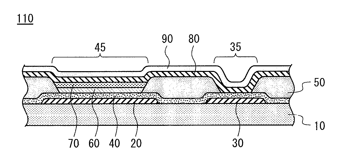
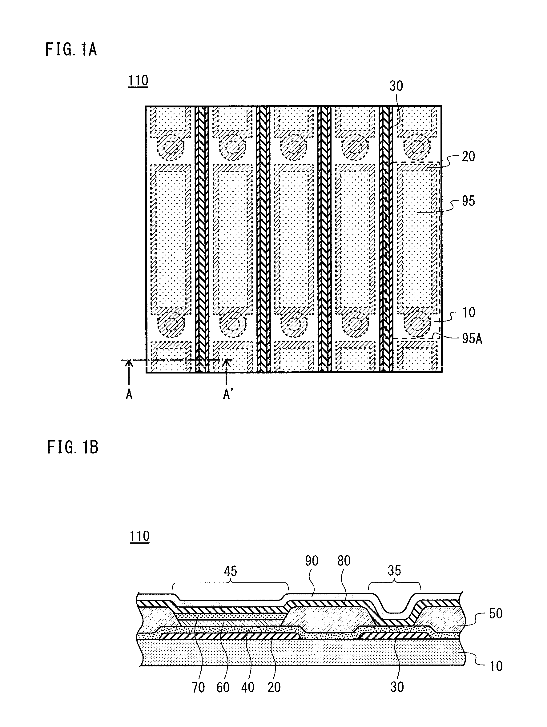
[0126]FIGS. 1A and 1B illustrate an organic EL display panel according to an aspect of the present invention. FIG. 1A is a partial plan view illustrating the main portions of the organic EL display panel. FIG. 1B is a cross-sectional diagram, along the line from A to A′ in FIG. 1A, illustrating the main portions of the organic EL display panel.

[0127]As shown in FIG. 1A, an organic EL display panel 110 according to the present embodiment is provided with a matrix of a plurality of light-emitting pixels 95A each having a light-emitting cell 95. A plurality of anod...

Example

Embodiment 2

[0438]

[0439]FIG. 39A is a schematic cross-sectional view illustrating the structure of an organic EL display panel 110C according to the present embodiment. FIG. 39B is a partially expanded view near a hole injection layer 40C.

[0440]The organic EL display panel 110C is an application type display panel in which the functional layer is, for example, applied by a wet process. The hole injection layer 40C and a variety of functional layers that have a variety of functions and include organic material are layered together and placed between a pair of electrodes consisting of an anode 20C and a cathode 90C.

[0441]Specifically, the organic EL display panel 110C includes a substrate 10C having the following layered on the main side thereof in the following order: anodes 20C, ITO layers 25C, the hole injection layer 40C, buffer layers 60C, light-emitting layers 70C, electron injection layers 85C, the cathode 90C, and a sealing layer 95C. Furthermore, auxiliary wirings 30C are for...


PUM


Abstract

A hole injection layer and a second electrode are both formed to be continuous above a first electrode and above an auxiliary wiring. The hole injection layer contains a tungsten oxide. An UPS spectrum, obtained from a UPS measurement, has a protrusion appearing near a Fermi surface and within a region corresponding to a binding energy range lower than a top of a valence band, and the tungsten oxide satisfies a condition, determined from an XPS measurement, that a ratio in a number density of atoms other than tungsten atoms and oxygen atoms to the tungsten atoms does not exceed 0.83.

Description

TECHNICAL FIELD[0001]The present invention relates to an organic EL (electroluminescence) display panel and an organic EL display apparatus utilizing an organic electric-field light-emitting element (referred to hereinafter as an “organic EL element”), which is an electric light emitter.BACKGROUND ART[0002]In recent years, progress is being made in research and development of diverse functional elements which involve the use of an organic semiconductor. One typical example of a functional element is an organic EL element. An organic EL element is a current-driven light emitter, and commonly has a pair of electrodes, namely an anode and a cathode, and functional layers layered between the pair of electrodes. The functional layers include a light-emitting layer composed of an organic material. Upon application of voltage across the pair of electrodes, holes injected from the anode to the functional layers recombine with electrons injected from the cathode to the functional layers. The...

Claims


Application Information

Patent Timeline
IPC IPC(8): H01L27/32
CPCH01L27/3297H10K59/12H10K59/1315H10K59/131H10K50/17H10K50/814H10K50/824
Inventor OHUCHI, SATORUKOMATSU, TAKAHIROYAMADA, RYUUTAFUJITA, HIROFUMIFUJIMURA, SHINYANISHIYAMA, SEIJINENDAI, KENICHISUGANO, KOUYADA, SHUHEI
Owner JOLED INC
Why Eureka
Try Eureka