Position estimating apparatus, position estimating method, and computer program product

a technology of position estimation and position estimation, applied in the direction of location information based services, instruments, measurement devices, etc., can solve the problems of difficult use inside buildings and underground that are out of the range of wireless signals from satellites, and the position estimation technology based on gps positioning requires a long time, so as to suppress the effect of the accuracy of position estimation

Active Publication Date: 2013-06-06
SONY CORP
View PDF3 Cites 36 Cited by
  • Summary
  • Abstract
  • Description
  • Claims
  • Application Information

AI Technical Summary

Benefits of technology

[0049]According to embodiments of the present disclosure described above, it is possible to suppress a fall in the precision of position estimation.

Problems solved by technology

However, position estimating technology based on GPS positioning requires a long time at startup for supplementary synchronization and is difficult to use inside buildings and underground that are out of range for the wireless signals from satellites.

Method used


Image

  • Position estimating apparatus, position estimating method, and computer program product
  • Position estimating apparatus, position estimating method, and computer program product
  • Position estimating apparatus, position estimating method, and computer program product

Examples


first embodiment

2. FIRST EMBODIMENT

[0109]2-1. Configuration of Wireless Terminal According to First Embodiment

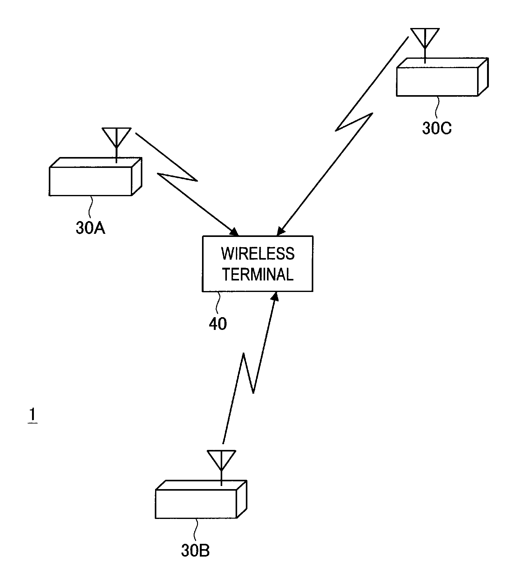
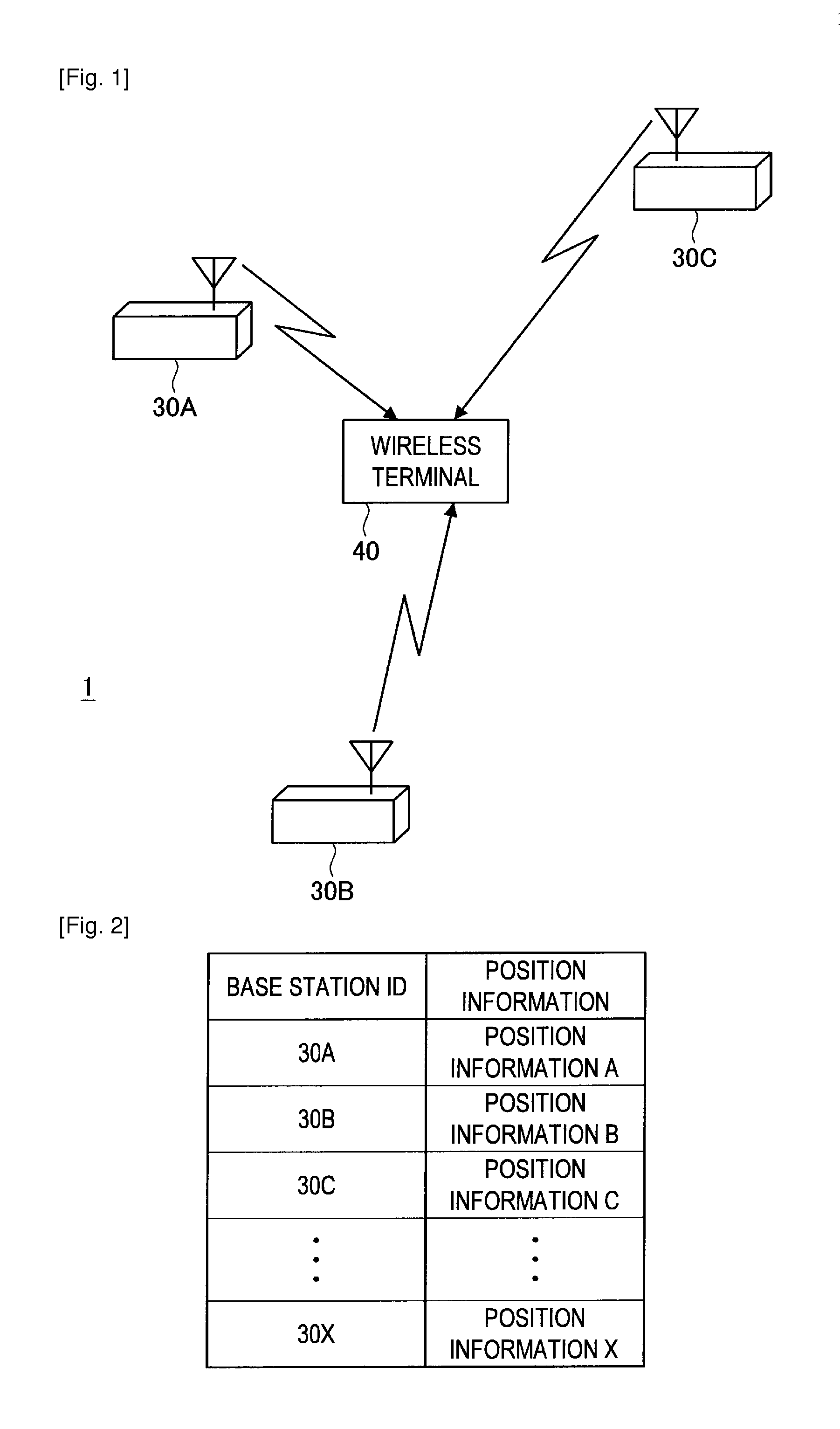
[0110]FIG. 5 is a functional block diagram showing the configuration of a wireless terminal 40-1 according to a first embodiment of the present disclosure. As shown in FIG. 5, the wireless terminal 40-1 according to the first embodiment includes a communication unit 412, a measurement unit 414, a base station information storage unit 416, an accelerometer 420, a moved distance calculating unit 424, an estimation result storage unit 428, a reference area determining unit 432, and a position estimating unit 436. Although described in detail later, the wireless terminal 40-1 according to the first embodiment encompasses a function as a position estimating apparatus that estimates the position of the wireless terminal 40-1.

[0111]The communication unit 412 is an interface for base stations 30 in the periphery of the wireless terminal 40-1 and functions as a reception unit that receives wireless ...

second embodiment

3. SECOND EMBODIMENT

[0128]The first embodiment of the present disclosure has been described above. Next, a second embodiment of the present disclosure will be described. As described in detail below, the second embodiment of the present disclosure differs to the first embodiment in that the reference area is determined in accordance with a position determination result produced by a different method to the position estimating unit 436.

[0129]3-1: Configuration of Wireless Terminal According to Second Embodiment

[0130]FIG. 9 is a functional block diagram showing the configuration of a wireless terminal 40-2 according to the second embodiment of the present disclosure. As shown in FIG. 9, the wireless terminal 40-2 according to the second embodiment includes the communication unit 412, the measurement unit 414, the base station information storage unit 416, a GPS positioning unit 440, and a reference area determining unit 444. Note that since functional blocks such as the communication ...

third embodiment

4. THIRD EMBODIMENT

[0142]The second embodiment of the present disclosure has been described above. Next, a wireless terminal 40-3 according to a third embodiment of the present disclosure will be described in detail with reference to FIGS. 12 to 16.

[0143]4-1: Configuration of Wireless Terminal According to Third Embodiment

[0144]FIG. 12 is a functional block diagram showing the configuration of the wireless terminal 40-3 according to the third embodiment of the present disclosure. As shown in FIG. 12, the wireless terminal 40-3 according to the third embodiment includes the communication unit 412, the measurement unit 414, the base station information storage unit 416, the GPS positioning unit 440, the reference area determining unit 444, a low reliability base station information storage unit 448, a mobile base station determining unit 452, and a mobile base station information storage unit 456.

[0145]Note that since functional blocks such as the communication unit 412, the measureme...


PUM


Abstract

An apparatus, method and computer program storage device cooperate to provide a quality position estimation of a mobile communication device by determining a reference area. The reference area includes the position of the mobile communication device as well as a plurality of transmitters. Transmitters that are detected as being outside of the reference area are excluded from contributing to the position estimate. The reference area is centered at a standard position, which may be a previous position or a GPS based position, for example. The range of the reference area includes a component that considers the range of a transmitter, as well as a GPS error or an estimated move distance of the mobile communication device.

Description

TECHNICAL FIELD[0001]The present disclosure relates to a position estimating apparatus, a position estimating method, and a computer program product.BACKGROUND ART[0002]Recently, receiver apparatuses capable of receiving wireless signals transmitted from satellites have been installed in moving bodies such as vehicles, mobile telephones, and the like. By using GPS (Global Positioning System) positioning, it is possible to estimate the position of the moving body in which the receiver apparatus is installed. Such position estimating technology that uses a receiver apparatus is an important base technology in a wide range of fields such as navigation, security and entertainment. However, position estimating technology based on GPS positioning requires a long time at startup for supplementary synchronization and is difficult to use inside buildings and underground that are out of range for the wireless signals from satellites.[0003]Also, as disclosed in Japanese Laid-Open Patent Public...

Claims


Application Information

Patent Timeline
Patent Type & Authority Applications(United States)
IPC IPC(8): H04W4/02G01S5/02G01S5/14G01S19/12
CPCG01C21/28H04W4/02G01S5/14H04W64/00
Inventor MITSUYA, KOSHIROSHIONOZAKI, ATSUSHI
Owner SONY CORP
Why Eureka
Try Eureka