pneumatic tire

A technology for pneumatic tires and treads, used in tire parts, treads, transportation and packaging, and can solve problems affecting quality and production costs

Active Publication Date: 2018-06-01
SUMITOMO RUBBER IND LTD
View PDF6 Cites 0 Cited by
  • Summary
  • Abstract
  • Description
  • Claims
  • Application Information

AI Technical Summary

Problems solved by technology

However, by adding the above-mentioned reinforcing parts or adopting a larger thickness, quality and production cost will be affected
There is a limit to improving the durability of tires that have been put into a market where price competition is fierce, as in the past.

Method used


Image

  • pneumatic tire
  • pneumatic tire

Examples


Embodiment 1

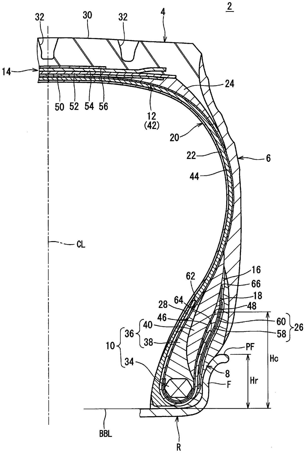
[0108] obtained with figure 1 A heavy-duty pneumatic tire according to Example 1 having the basic structure shown and the specifications shown in Table 1 below. The size of the tires is 12.00R20. The tire has a first filler. This situation is represented by "Y" in the first glue column of the table. A cord composed of nylon fibers was used for the cord contained in the first filler. The height in the radial direction from the bead base line to the outer end of the first filler was set at 95 mm. The height in the radial direction from the bead base line to the outer end of the hard portion was set to 90 mm. The radial direction height Hc from the bead base line to the end of the turnback portion was set to 75 mm. The size of the rim on which this tire was assembled was 8.8×20, and the height Hr of the flange of the rim was 45 mm.

Embodiment 2-5 and comparative example 2-3

[0112] Tires of Examples 2-5 and Comparative Examples 2-3 were obtained in the same manner as in Example 1 except that the height Hc was adjusted to set the ratio (Hc / Hr) as shown in Tables 1 and 2 below.

Embodiment 6 and comparative example 4-5

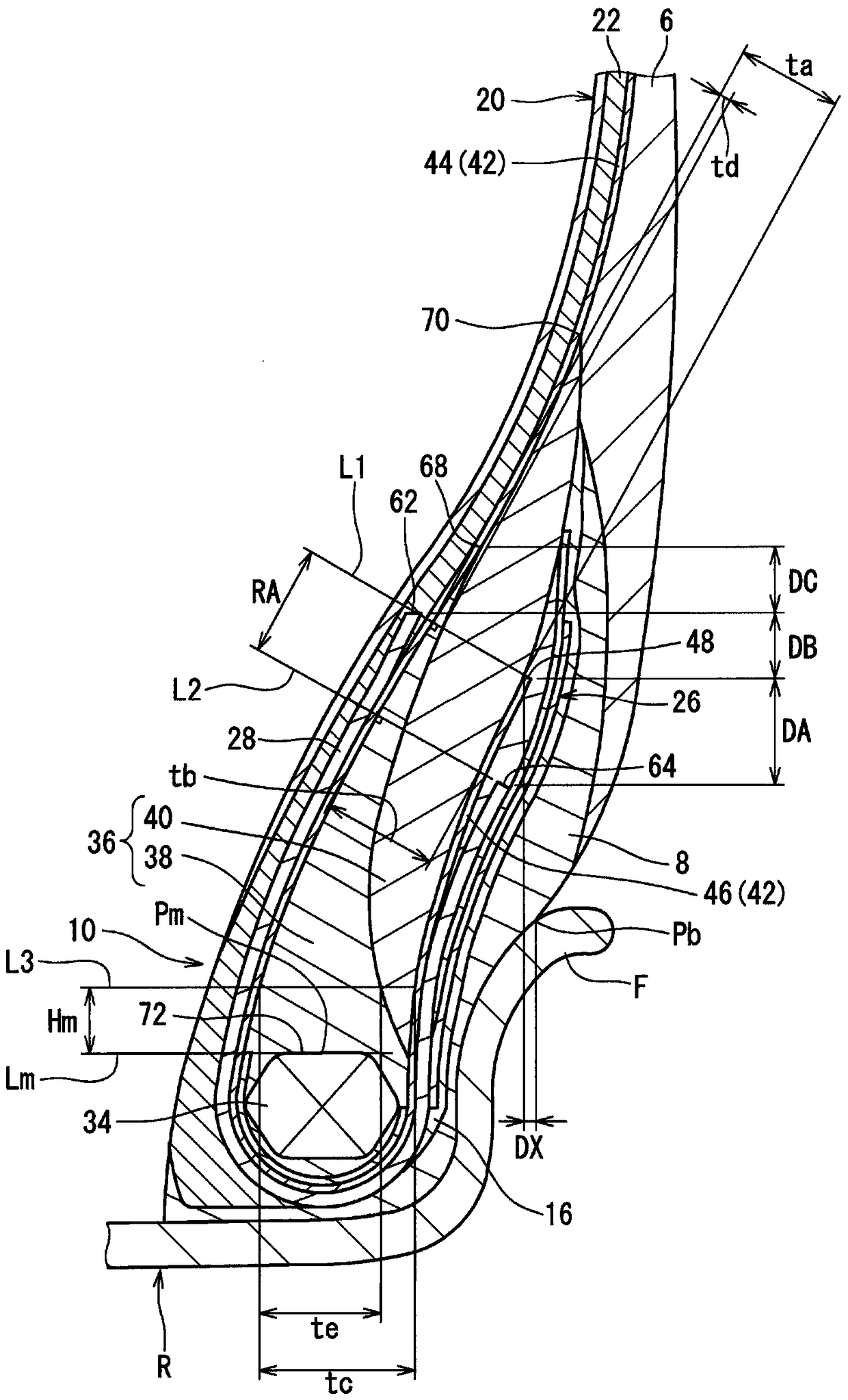
[0114] Tires of Example 6 and Comparative Examples 4-5 were obtained in the same manner as in Example 1 except that the distance DB was set as in Table 2 below.


PUM


Abstract

The present invention provides a pneumatic tire in which durability is improved. In this tire, the turn-back portion (46) is located between the apex (36) and the first filling (26). The second filler (28) folds back around the bead core (34). The first end (62) of the second filler is located axially inward of the main portion (44). The second end (64) of the second filling is located between the turning portion (46) and the first filling. When the height of the flange of the rim is used as the reference height, the ratio of the height of the turn-back portion to the reference height is not less than 1.58 and not more than 1.75. When the end of the contact surface between the tire and the rim is used as a reference position, the end (48) of the turnback portion is axially aligned with the reference position, or located axially inward of the reference position. The first end of the second filler is consistent with the end of the folded portion in the radial direction, or is located on the outer side in the radial direction than the end of the folded portion.

Description

technical field [0001] The present invention relates to pneumatic tires. Specifically, the present invention relates to heavy-duty pneumatic tires used for trucks, buses, and the like. Background technique [0002] When a tire is pressed against the road, a load is applied to the tire. As a result, the bead portion is deformed so as to fall toward the flange side of the rim. When the tire leaves the road, the load is removed. As a result, the bead is partially restored. In a tire in a running state, deformation and restoration repeatedly occur at the bead portion. If the deformation and recovery are repeated, the portion of the bead is heated. Heat can affect the durability of the tire. [0003] The carcass of the tire has a carcass ply. The carcass ply is folded back around the bead core of the bead. The ends of the carcass ply may exist in the bead portion of the tire. In the case where the tire is provided with a filler, the end of the filler may also exist in th...

Claims


Application Information

Patent Timeline
Patent Type & Authority Patents(China)
IPC IPC(8): B60C15/00B60C15/06
Inventor 沼田一起
Owner SUMITOMO RUBBER IND LTD
Why Eureka
Try Eureka