Artificial Lighting System

Inactive Publication Date: 2013-07-25
OVERTURF MATTHEW
View PDF11 Cites 20 Cited by
  • Summary
  • Abstract
  • Description
  • Claims
  • Application Information

AI Technical Summary

Benefits of technology

[0006]The artificial lighting system may also include a cooling system having a fan device and an exhaust and/or intake vent, or connections for

Problems solved by technology

When a light source emits light, large amounts of heat may be produced because of the en

Method used


Image

  • Artificial Lighting System
  • Artificial Lighting System
  • Artificial Lighting System

Examples


Example

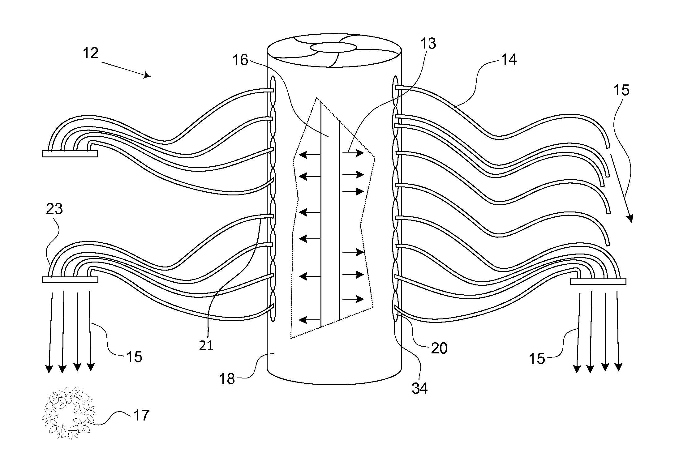
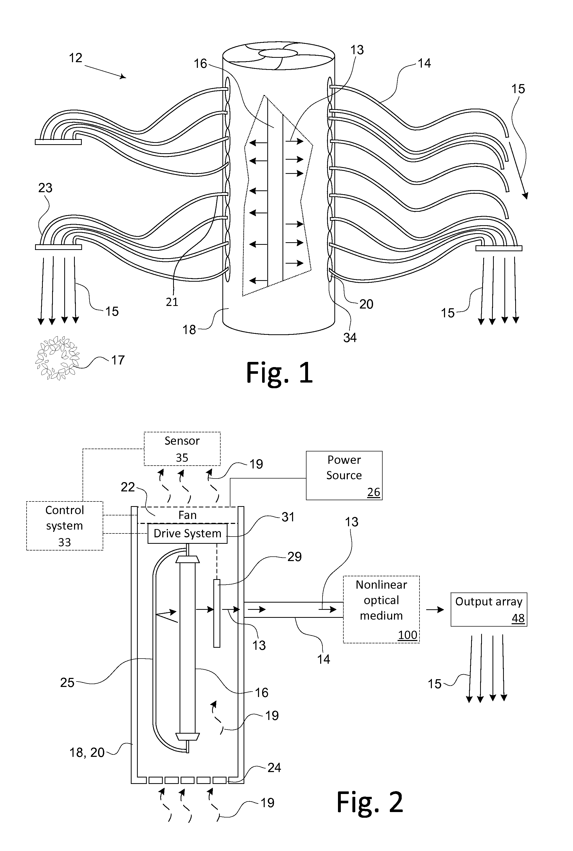
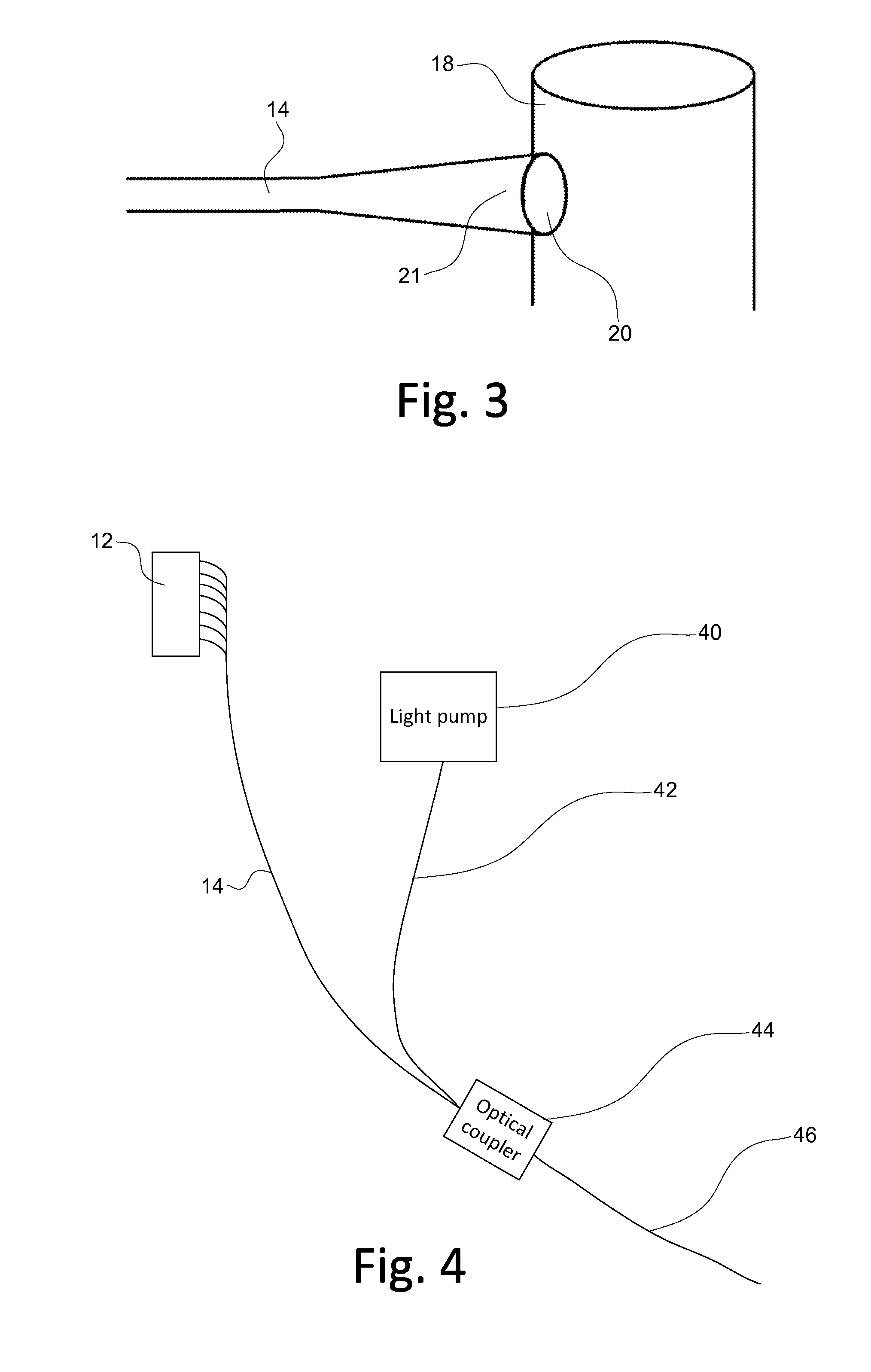
[0014]An artificial lighting system is described herein and illustrated in the accompanying figures. The artificial lighting system generates electromagnetic radiation at a source location, and outputs the electromagnetic radiation at a target location. The output is in the form of electromagnetic radiation in the visible spectrum and / or photosynthetically active radiation. In some embodiments, the electromagnetic radiation is focused and distributed through one or more lenses to provide increased intensity. For target locations that are physically remote from the source location, optical waveguides and components distribute the electromagnetic radiation. Some embodiments incorporate an automated emitter allowing the output of the artificial lighting system to be moved at the target location. The artificial lighting system seeks to provide high intensity electromagnetic radiation to the target while minimizing the exposure of the target to the heat generated by the light source.

[001...


PUM


Abstract

An artificial lighting system. The artificial lighting system generates electromagnetic radiation at a source location, and outputs the electromagnetic radiation at a target location. The output is in the form of electromagnetic radiation in the visible spectrum and/or photosynthetically active radiation. In some embodiments, the electromagnetic radiation is focused and distributed through one or more lenses to provide increased intensity. For target locations that are physically remote from the source location, optical waveguides and components distribute the electromagnetic radiation. Some embodiments incorporate an automated emitter allowing the output of the artificial lighting system to be moved at the target location. The artificial lighting system seeks to provide high intensity electromagnetic radiation to the target while minimizing the exposure of the target to the heat generated by the light source.

Description

BACKGROUND[0001]Artificial lighting provides a valuable source of light for household and agricultural applications. Generally, the light emitted from a light source will lose intensity as it radiates from the source in various directions. The light emitted is dispersed in all directions and may be absorbed by the walls and ceiling of a room, further reducing the intensity of the light. Additionally, to provide light to a desired area, the light source generally must be in close proximity to the area to be lit. When a light source emits light, large amounts of heat may be produced because of the energy required by the light source and inefficiencies in converting the energy into light.[0002]What is needed therefore is an efficient lighting system that provides the ability to direct focused light to a point remote from a light source and where the intensity of the light does not substantially decrease as the light travels from the source to the desired location. Further, excess heat ...

Claims


Application Information

Patent Timeline
IPC IPC(8): F21V8/00F21V29/02F21V13/02
CPCG02B6/0008F21V13/02A01G9/26F21V29/677F21V23/0442A01G7/045G02B6/0006F21S8/061A01G9/249Y02P60/14
Inventor OVERTURF, MATTHEW
Owner OVERTURF MATTHEW
Why Eureka
Try Eureka