AI technical title is built by Patsnap AI team. It summarizes the technical point description of the patent document.
a technology of pelvic implants and urethra, which is applied in the field of pelvic implant systems and methods, can solve the problems of incontinence, type of incontinence, and incontinence, and achieve the effect of controlling and eliminating the rotation of the urethra
Inactive Publication Date: 2013-08-08
BOSTON SCI SCIMED INC
View PDF10 Cites 8 Cited by
Summary
Abstract
Description
Claims
Application Information
AI Technical Summary
This helps you quickly interpret patents by identifying the three key elements:
Problems solved by technology
Method used
Benefits of technology
Benefits of technology
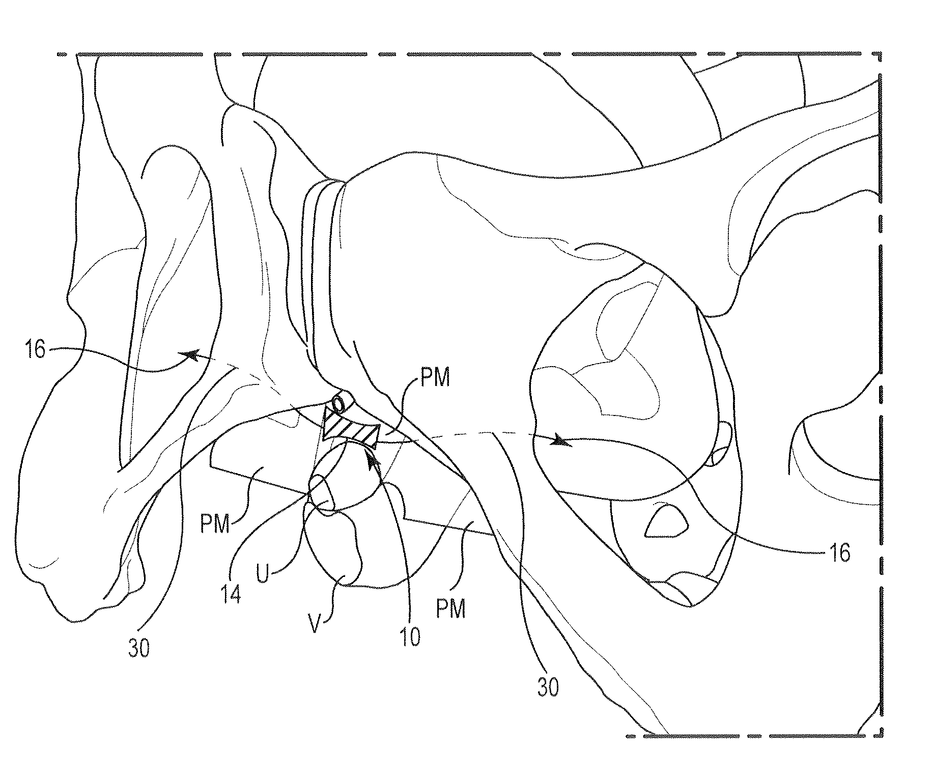
[0011]The present invention can include surgical instruments, implantable articles, and methods for urological applications, particularly for the treatment of stress and / or urge urinary incontinence, fecal incontinence, and prolapse by implanting a constraining device. The constraining device or implant can control and eliminate rotation of the urethra that is associated with incontinence.
[0012]Embodiments of the present invention can include apparatus and methods for treating urinary incontinence, fecal incontinence, and other pelvic defects or dysfunctions, in both males and females using one or more implants to reinforce the supportive tissue of the urethra. The implants are configured to engage and pull (e.g., pull up or down) or reposition the supportive tissue, such as the perineal membrane. The perineal membrane is the fibrous membrane in the perineum that intersects the urethra and vagina near the midurethra location and can thus be stabilized or controlled in a manner that helps restore continence. As such, systems, methods and implants can be utilized to eliminate the need for mesh or other supportive structures directly engaging under the urethra that is common with other incontinence slings. The implants can be shaped to facilitate such support, e.g., provided with anchoring end portions, barbs or other devices of many available shapes and configurations. One or more anchors or tissue engagement portions can be employed to attach and stabilize the implants or devices to tissue.
[0013]Embodiments of the present invention can provide smaller implants or devices, fewer implant or device components, thus reducing the size and number of incisions, improving implant manipulation and adjustment, the complexity of the insertion and deployment steps, and healing times.
[0018]The medial device can spread or better distribute the tension load over a larger surface compared to a thin edge surface. This, in turn, promotes stability of the implant and connecting suture and, ultimately, the target support tissue.
Problems solved by technology
Urinary incontinence may occur when the muscles of the urinary system are injured, malfunction or are weakened.
Other factors, such as trauma to the urethral area, neurological injury, hormonal imbalance or medication side-effects, may also cause or contribute to incontinence.
Inappropriate bladder contractions and weakened sphincter muscles usually cause this type of incontinence.
Functional incontinence results when a person has difficulty moving from one place to another.
Fecal incontinence, like urinary incontinence, has proven to be challenging to treat.
Other patients, though, are considered to have neurogenic or idiopathic fecal incontinence, and efforts to treat these patients has been less successful.
Success has been limited, and the various treatment modalities can result in morbidity.
Method used
Image
Click on the blue label to locate the original text in one second.
Reading with bidirectional positioning of images and text.
Examples
Embodiment Construction
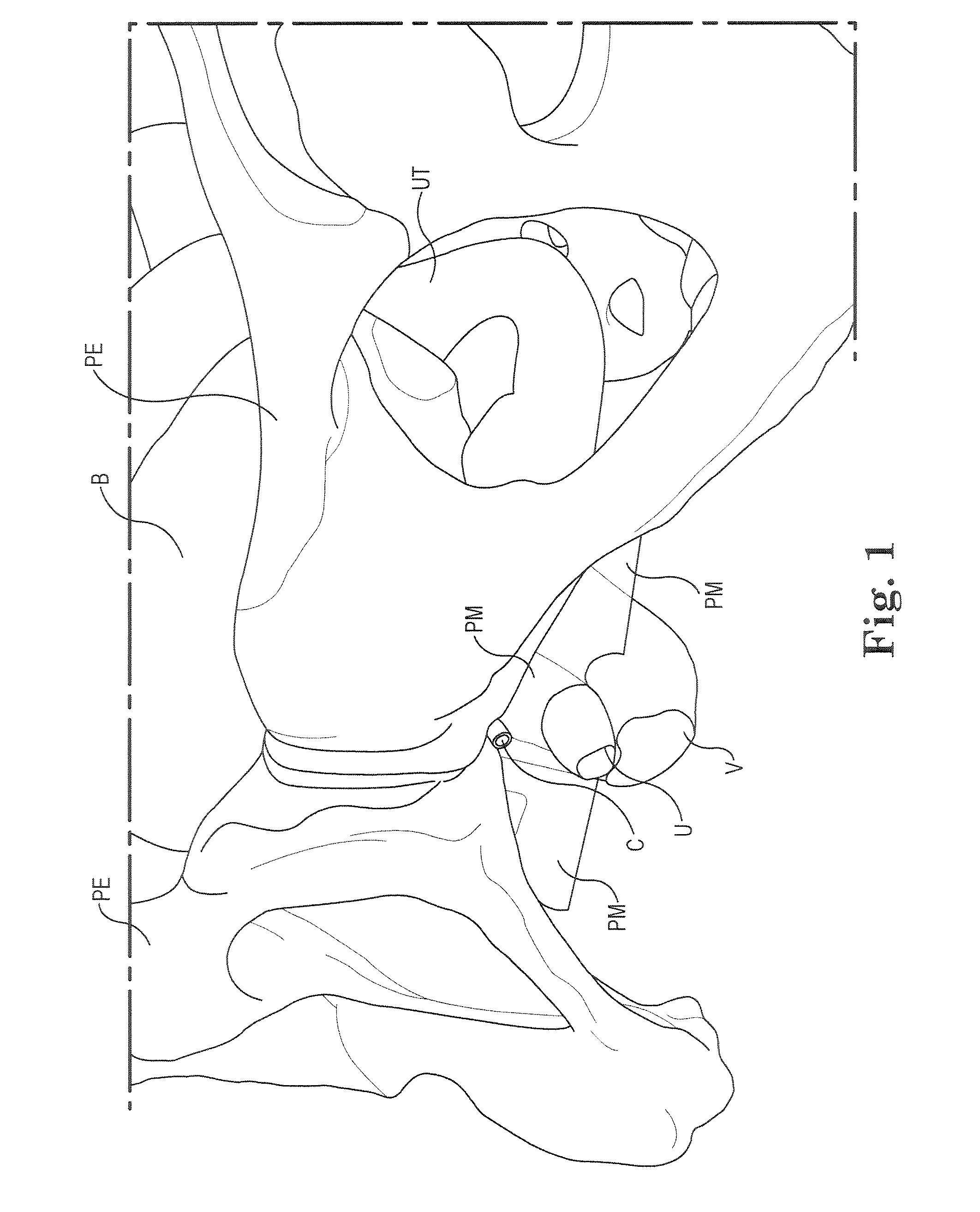
[0043]FIG. 1 shows a schematic view of relevant portions of the female pelvic region, and the urinary and reproductive system, including the pelvis PE, vagina V, uterus UT, urethra U, bladder B and the deep clitoral vein C. Further, a portion of the perineal membrane PM is shown at the midurethra / distal location, providing a viable paraurethral target for stabilizing or controlling the position and movement of the urethra to assist in restoring continence.
[0044]Embodiments of the present invention can include apparatus and methods for treating urinary incontinence, fecal incontinence, and other pelvic defects or dysfunctions, in both males and females using one or more lateral implants to reinforce the supportive tissue of the urethra. One or more implant devices 10 are configured to engage and pull (e.g., pull up) or reposition support tissue (e.g., paraurethral), such as the perineal membrane, uterovaginal fascia, endopelvic fascia, or other anatomical features at which connective...
PUM
Abstract
Systems and methods are provided and adapted to engage and pull (e.g., pull up) or reposition urethral support tissue, such as the portion of the perineal membrane above or below the urethra. The perineal membrane intersects the urethra and vagina at the midurethra or distal location and can thus be stabilized or controlled in a manner that helps restore continence.
Description
PRIORITY[0001]This application claims priority to and the benefit of U.S. Provisional Patent Application No. 61 / 515,180, filed Aug. 4, 2011, U.S. Provisional Patent Application No. 61 / 545,104, filed Oct. 7, 2011, U.S. Provisional Patent Application No. 61 / 547,467, filed Oct. 14, 2011, U.S. Provisional Patent Application No. 61 / 547,503, filed Oct. 14, 2011, U.S. Provisional Patent Application No. 61 / 607,332, filed Mar. 6, 2012, U.S. Provisional Patent Application No. 61 / 607,891, filed Mar. 7, 2012, U.S. Provisional Patent Application No. 61 / 608,436, filed Mar. 8, 2012, U.S. Provisional Patent Application No. 61 / 608,478, filed Mar. 8, 2012, U.S. Provisional Patent Application No. 61 / 653,199, filed May 30, 2012, U.S. Provisional Patent Application No. 61 / 653,213, filed May 30, 2012, U.S. Provisional Patent Application No. 61 / 653,224, filed May 30, 2012, U.S. Provisional Patent Application No. 61 / 653,236, filed May 30, 2012; with each of the above-referenced applications and disclosures...
Claims
Application Information
Patent Timeline
Application Date:The date an application was filed.
Publication Date:The date a patent or application was officially published.
First Publication Date:The earliest publication date of a patent with the same application number.
Issue Date:Publication date of the patent grant document.
PCT Entry Date:The Entry date of PCT National Phase.
Estimated Expiry Date:The statutory expiry date of a patent right according to the Patent Law, and it is the longest term of protection that the patent right can achieve without the termination of the patent right due to other reasons(Term extension factor has been taken into account ).
Invalid Date:Actual expiry date is based on effective date or publication date of legal transaction data of invalid patent.
Patent Type & AuthorityApplications(United States)

