Pelvic Implant System and Method

Active Publication Date: 2013-01-24
BOSTON SCI SCIMED INC
View PDF10 Cites 31 Cited by
  • Summary
  • Abstract
  • Description
  • Claims
  • Application Information

AI Technical Summary

Benefits of technology

The present invention provides surgical instruments, implantable articles, and methods for treating urinary and fecal incontinence and prolapse by implanting a paraurethral constraining device. The device can control and eliminate rotation of the ureter that is associated with incontinence. The invention can offer smaller implants, fewer components, and a simplified insertion process, reducing the size and complexity of incisions and healing times. The final position of the implanted device creates a stable and suspended orientation, with the anchor distributing tension over a larger surface area, promoting stability and efficiency of the support tissue. The invention also minimizes the risk of infection, irritation, and interference with sexual activity by reducing or eliminating exposed material inside the vaginal cavity.

Problems solved by technology

Urinary incontinence may occur when the muscles of the urinary system are injured, malfunction or are weakened.
Other factors, such as trauma to the urethral area, neurological injury, hormonal imbalance or medication side-effects, may also cause or contribute to incontinence.
Inappropriate bladder contractions and weakened sphincter muscles usually cause this type of incontinence.
Functional incontinence results when a person has difficulty moving from one place to another.

Method used


Image

  • Pelvic Implant System and Method
  • Pelvic Implant System and Method
  • Pelvic Implant System and Method

Examples


Embodiment Construction

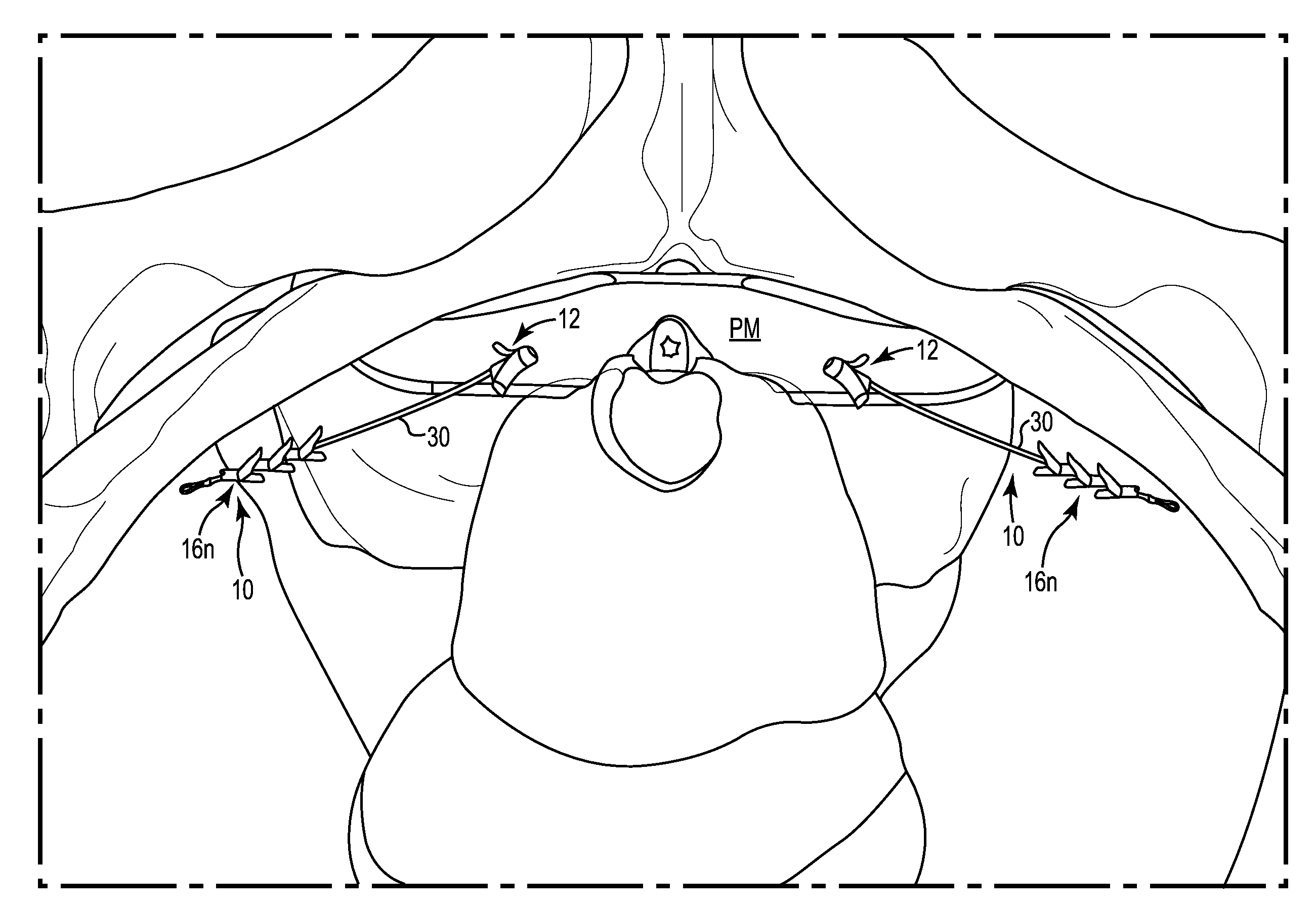
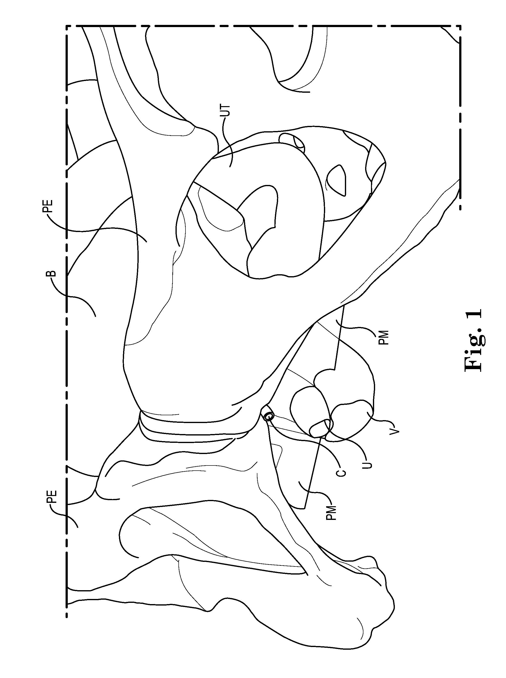
[0059]FIG. 1 shows a schematic view of relevant portions of the female pelvic region, and the urinary and reproductive system, including the pelvis PE, vagina V, uterus UT, urethra U, bladder B and the deep clitoral vein C. Further, a portion of the perineal membrane PM is shown at the midurethra / distal location, providing a viable paraurethral target for stabilizing or controlling the position and movement of the urethra to assist in restoring continence.

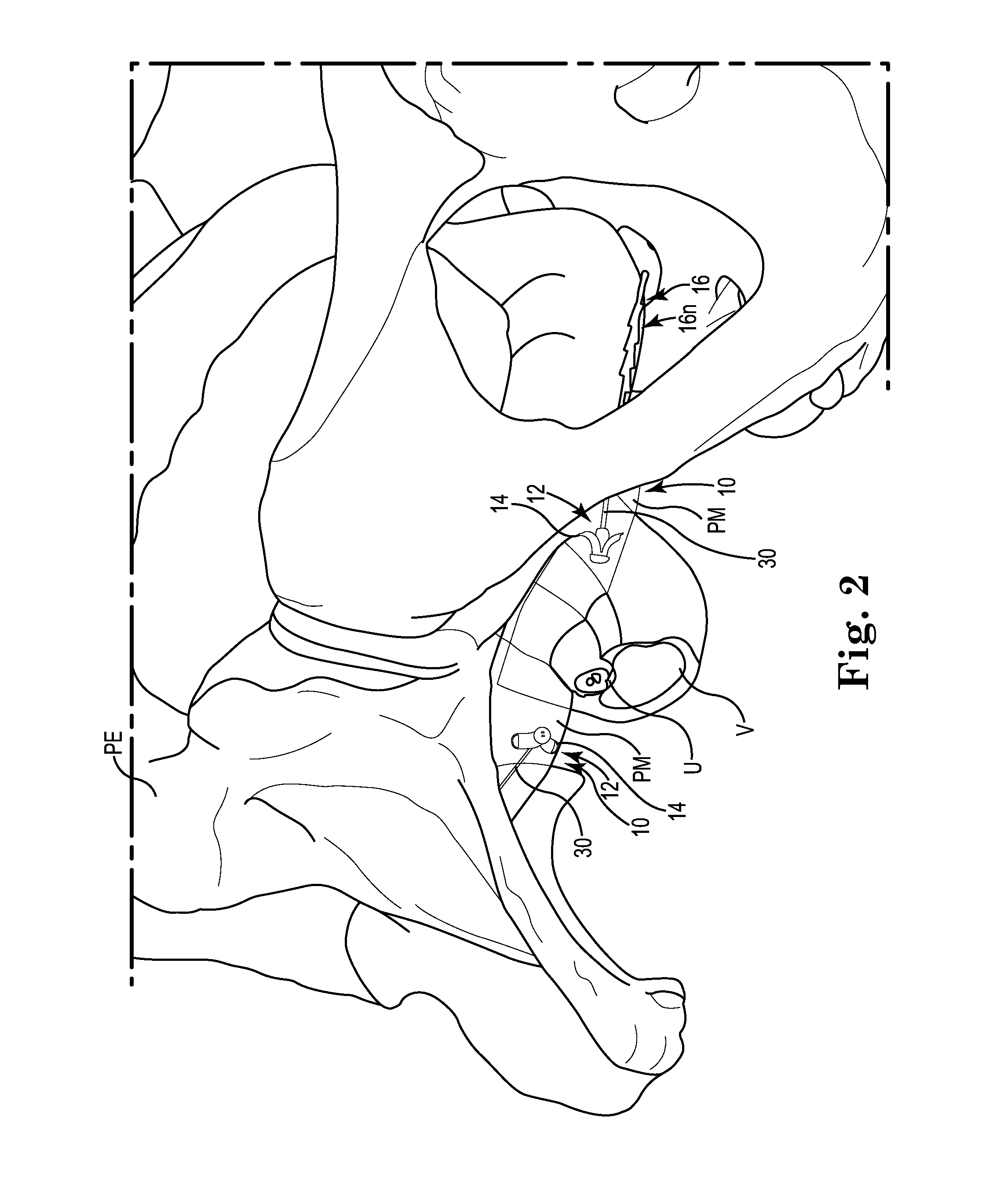
[0060]Embodiments of the present invention can include apparatus and methods for treating urinary incontinence, fecal incontinence, and other pelvic defects or dysfunctions, in both males and females using one or more lateral implants to reinforce the supportive tissue of the urethra. One or more implant devices 10 are configured to engage and pull (e.g., pull up) or reposition support tissue (e.g., paraurethral), such as the perineal membrane, uterovaginal fascia, endopelvic fascia, or other anatomical features at which connective...


PUM


Abstract

Systems and methods are provided and adapted to engage and pull (e.g., pull up) or reposition paraurethral support tissue, such as the perineal membrane. The perineal membrane intersects the urethra and vagina at the midurethra or distal location and can thus be stabilized or controlled in a manner that helps restore continence. As such, the implants can be utilized to eliminate the need for mesh or other supportive structures under the urethra that is common with other incontinence slings.

Description

PRIORITY[0001]This application claims priority to and the benefit of U.S. Provisional Patent Application No. 61 / 510,726, filed Jul. 22, 2011, U.S. Provisional Patent Application No. 61 / 515,180, filed Aug. 4, 2011, U.S. Provisional Patent Application No. 61 / 545,104, filed Oct. 7, 2011, U.S. Provisional Patent Application No. 61 / 547,467, filed Oct. 14, 2011, U.S. Provisional Patent Application No. 61 / 547,503, filed Oct. 14, 2011, U.S. Provisional Patent Application No. 61 / 607,332, filed Mar. 6, 2012, U.S. Provisional Patent Application No. 61 / 607,891, filed Mar. 7, 2012, U.S. Provisional Patent Application No. 61 / 608,436, filed Mar. 8, 2012, U.S. Provisional Patent Application No. 61 / 608,478, filed Mar. 8, 2012, U.S. Provisional Patent Application No. 61 / 653,199, filed May 30, 2012, U.S. Provisional Patent Application No. 61 / 653,213, filed May 30, 2012, U.S. Provisional Patent Application No. 61 / 653,224, filed May 30, 2012, and U.S. Provisional Patent Application No. 61 / 653,236, filed...

Claims


Application Information

Patent Timeline
IPC IPC(8): A61F2/04
CPCA61F2/0036A61F2/0045A61B17/0401A61B2017/00805A61B2017/00867A61B2017/06176A61B2017/0412A61B2017/0417A61B2017/0496A61B2017/06052A61B2017/0409A61F2210/0014A61F2220/0016A61B17/3468A61B2017/0464
Inventor ALLEN, JOHN J.MUJWID, JAMES R.ARNAL, KEVIN R.FELTON, JESSICA E.LUND, ROBERT E.
Owner BOSTON SCI SCIMED INC
Why Eureka
Try Eureka