Friction adjustment mechanism for a support apparatus

a technology of friction adjustment and support apparatus, which is applied in the field of furniture or fixtures, can solve the problems of failure to hold objects of substantial weight, the monitor arms are often unable to permit monitors of over 25 pounds, and the mechanism used to retain the position of the tilted object is not suitable for use. , to achieve the effect of increasing or decreasing the amount of for

Active Publication Date: 2013-08-29
KNOLL INC
View PDF12 Cites 16 Cited by
  • Summary
  • Abstract
  • Description
  • Claims
  • Application Information

AI Technical Summary

Benefits of technology

[0007]A support apparatus is provided that is configured to adjustably position an object such as a monitor, liquid crystal display, television, light, display device, tablet, or other object. The support apparatus may include an arm assembly attached to a mounting body. A pivotal attachment may be formed between the arm assembly and the mounting body to permit the mounting body to be tilted relative to the arm assembly. A friction adjustment mechanism may be attached to the pivotal attachment to permit a user to adjust an amount of friction induced by tilting of the monitor, which may increase or decrease the amount of force needed to tilt the held object. Adjustment of the friction that is induced by such tilting may also help ensure that an object held by the support apparatus may be maintained in a desired tilted position.

Problems solved by technology

The mechanisms used to retain the position of the tilted object, however, often fails to hold objects that have substantial weight.
For instance, monitor arms often are unable to permit a monitor of over 25 pounds to be tilted to a desired position by directly moving the monitor upwards or downwards about an axle.
Instead, such monitors often have to be supported so that they cannot be directly tilted upward or downwards.
Other portions of the arm must be tilted or moved to adjust where the monitor may be positioned, which may require a user to exert a significant amount of time to make a simple adjust to a monitor's position.

Method used


Image

  • Friction adjustment mechanism for a support apparatus
  • Friction adjustment mechanism for a support apparatus
  • Friction adjustment mechanism for a support apparatus

Examples


Embodiment Construction

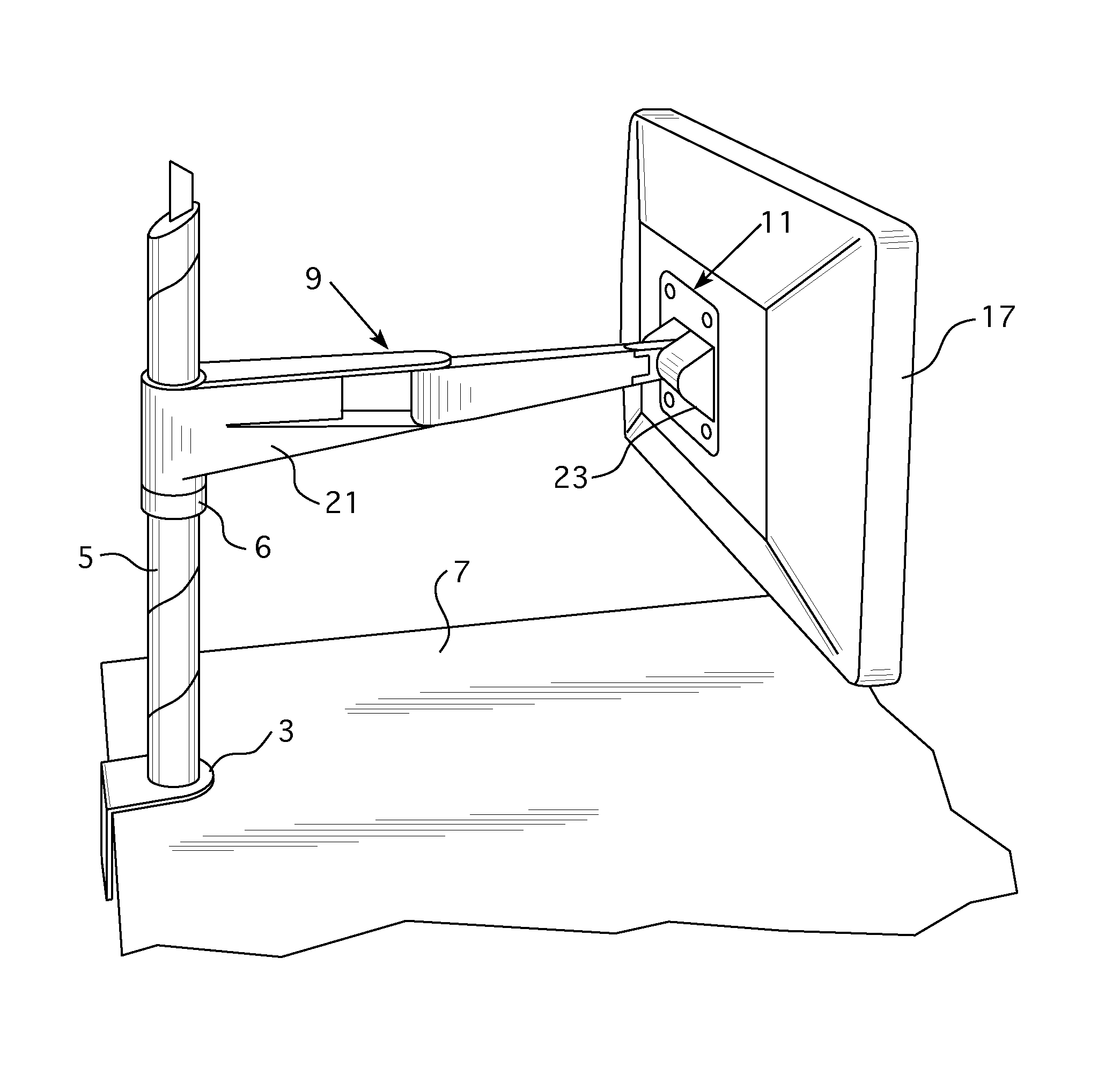
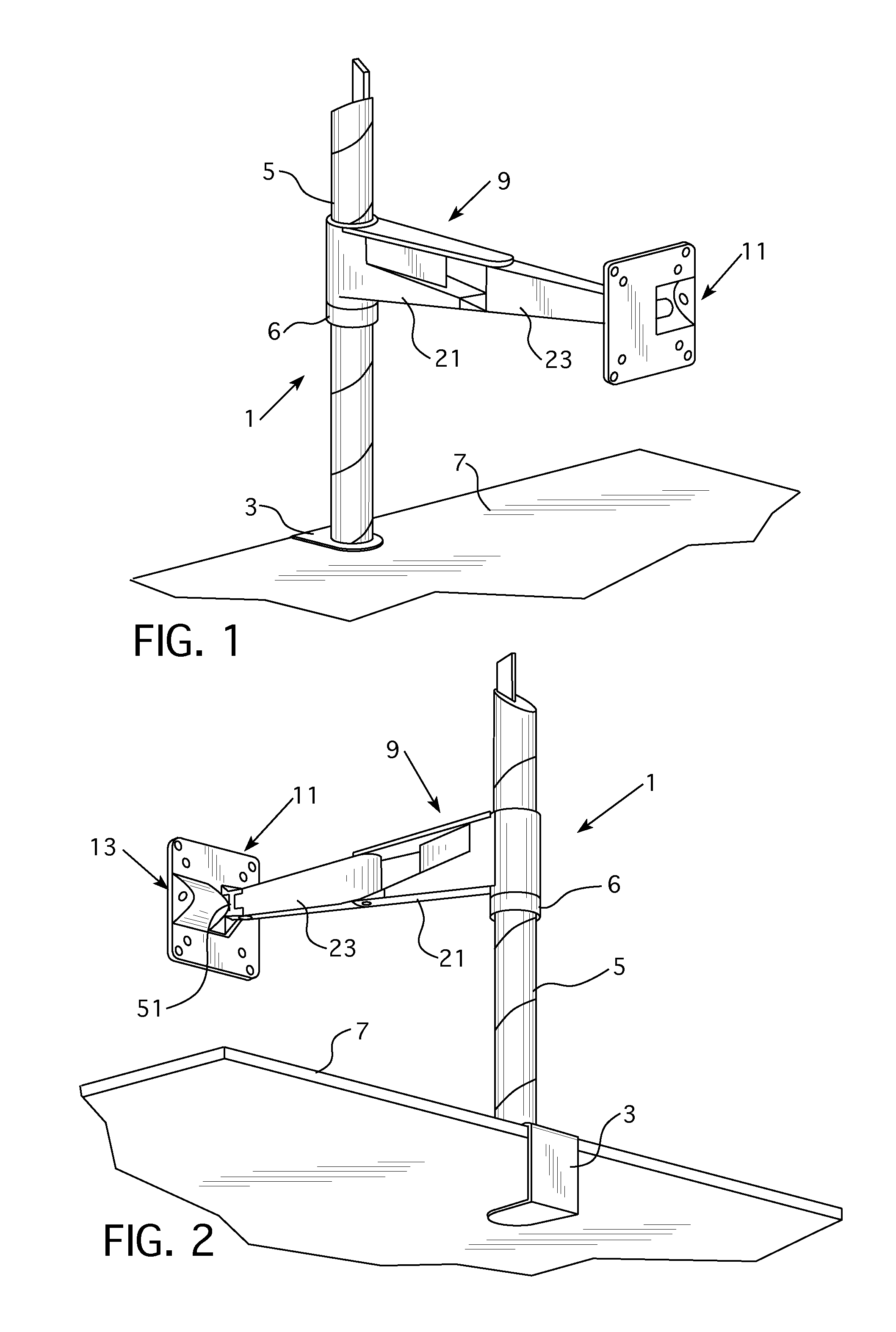
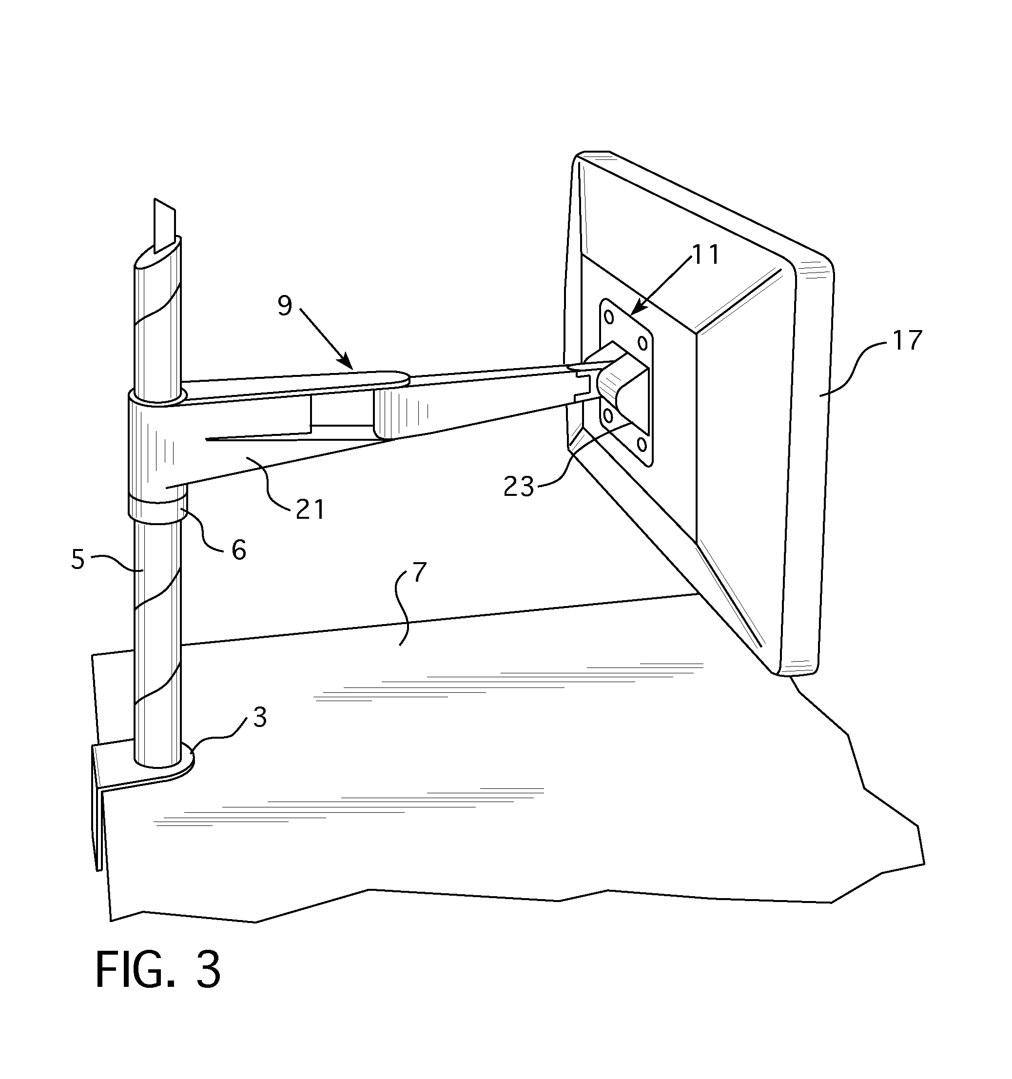
[0030]Referring to FIGS. 1-7, a support apparatus 1 may include a support post 5 that is attached to a work surface 7 by a clamp or other mounting device 3. The work surface 7 may be a table, desk, or other article of furniture about which someone may work.

[0031]An arm assembly 9 is connected to the support post 5. The arm assembly may be vertically adjustable about the post 5 to adjust a height of the arm assembly 9. For instance, a portion of the arm assembly may rest on a vertically adjustable collar 6 that is positioned on the post and is moveable vertically on the post to adjust the vertical position of the arm assembly. The arm assembly 9 may be supported by the post 5 so that the arm assembly 9 is rotatable about the post 5. In alternative embodiments, the arm assembly may be connected to a gas spring and be adjustable horizontally and vertically via articulation points between different components of the arm assembly 9.

[0032]The arm assembly 9 may include a number of differe...


PUM


Abstract

A support apparatus includes an arm assembly attached to a mounting body. A frictional adjustment mechanism is provided between the mounting body and the arm assembly that permits an amount of friction induced by tilting of the mounting body to be adjusted so that a greater or lesser amount of force is needed by a user to tilt the mounting body and any object held by the mounting body. Preferably, the mounting body is configured to hold a monitor, liquid crystal display, or other display device.

Description

CROSS-REFERENCE TO RELATED APPLICATIONS[0001]The present application claims priority to U.S. Provisional Patent Application No. 61 / 538,327, which was filed on Sep. 23, 2011.FIELD OF INVENTION[0002]The present invention relates to furniture or fixtures such as monitor arms and support arms that are sized and configured to support copy holders, display devices, computer monitors, liquid crystal displays, televisions, lights, and other objects.BACKGROUND OF THE INVENTION[0003]Support arms such as monitor supports or copy holders often include one or more arms that extend from a support post. The arm is configured to hold an object, such as a monitor. The support post is typically clamped to a support surface, such as a desk, table or partition wall. Examples of support arms and similar support apparatuses are disclosed in U.S. Pat. Nos. 7,389,965, 7,252,277, 7,246,780, 7,182,301, 7,048,242, 7,014,157, 6,905,101, 6,863,252, 6,739,096, 6,679,096, 6,554,238, 6,554,235, 6,505,988, 6,499,70...

Claims


Application Information

Patent Timeline
Patent Type & Authority Applications(United States)
IPC IPC(8): F16M13/02
CPCF16M13/022F16M11/105F16M2200/022F16M11/24F16M11/2021
Inventor SAPPER, RICHARDSNYDER, RONALD
Owner KNOLL INC
Why Eureka
Try Eureka