Digital filter circuit and digital filter control method

a digital filter and control method technology, applied in the field of arithmetic processing circuits, can solve problems such as computation distortion, and achieve the effect of reducing circuit scale and electric power consumption

Active Publication Date: 2013-10-03
NEC CORP
View PDF2 Cites 6 Cited by
  • Summary
  • Abstract
  • Description
  • Claims
  • Application Information

AI Technical Summary

Benefits of technology

[0015]According to the present invention, in filter processing in a frequency domain of an overlap FDE method, the circuit scale and the electric power consumption can be reduced.

Problems solved by technology

Meanwhile, in FFT, it is assumed that a signal repeats periodically, it is a problem that a computation distortion occurs in a signal around both ends of a processing block of FFT.

Method used


Image

  • Digital filter circuit and digital filter control method
  • Digital filter circuit and digital filter control method
  • Digital filter circuit and digital filter control method

Examples


first exemplary embodiment

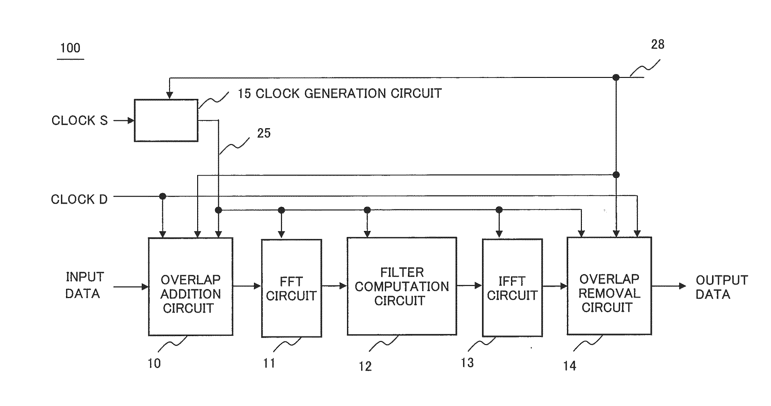
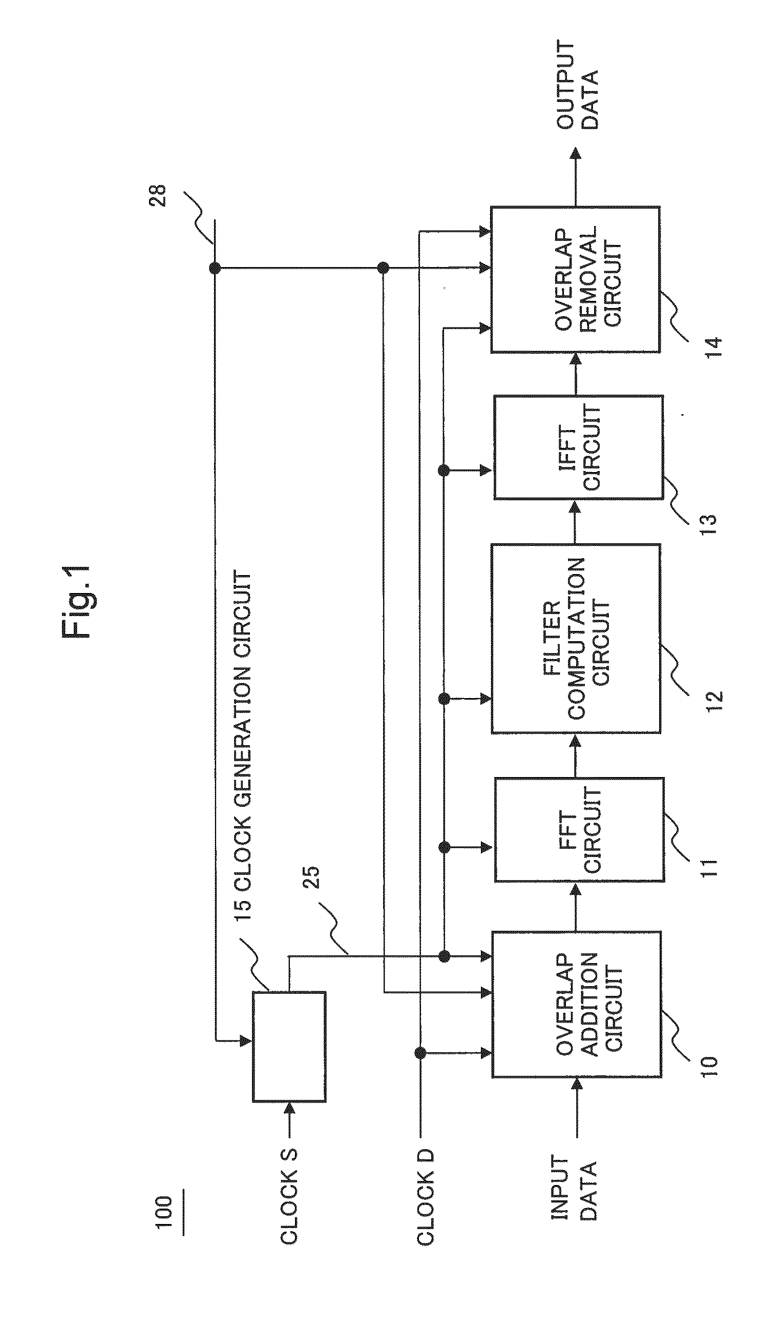
[0023]FIG. 1 is a block diagram showing an exemplary configuration of a digital filter circuit 100 according to a first exemplary embodiment of the present invention. The digital filter circuit 100 is a frequency domain filter circuit which performs filter processing in a frequency domain. Specifically, first, after transforming a signal, in a time domain, inputted as an input data to data in a frequency domain by FFT, the digital filter circuit 100 performs filter processing. After that, the digital filter circuit 100 retransforms the data to a signal data in the time domain by IFFT, and outputs the signal data as an output data.

[0024]For example, the digital filter circuit 100 refers to an overlap number setting signal 28 which is given from a higher level circuit (not shown) such as a CPU (Central Processing Unit) or the like, and determines the number of the overlap.

[0025]The digital filter circuit 100 includes an overlap addition circuit 10, a FFT circuit 11, a filter computati...

second exemplary embodiment

[0067]FIG. 4 is a block diagram showing an exemplary configuration of a digital filter circuit 101 according to a second exemplary embodiment of the present invention. The digital filter circuit 101 is a frequency domain filter circuit which performs filter processing in a frequency domain like the digital filter circuit 100 of the first exemplary embodiment. Basic operation of a frequency domain filter circuit has been already described in the first exemplary embodiment.

[0068]The digital filter circuit 101 refers to the overlap number setting signal 28 which is given from a higher level circuit such as a CPU like the digital filter circuit 100 of the first exemplary embodiment and determines the number of overlap.

[0069]The feature of the digital filter circuit 101 is that a setup table 36 is added to the digital filter circuit 100 of the first exemplary embodiment. Further, while the basic function of each component besides the setup table 36 is identical with each component in the...

third exemplary embodiment

[0107]FIG. 7 is a diagram showing an exemplary configuration of a digital filter circuit 1000 according to a third exemplary embodiment of the present invention. According to FIG. 7, the digital filter circuit 1000 includes an overlap addition means 1001, a FFT means 1002, a filter computation means 1003, an IFFT means 1004, an overlap removal means 1005 and a clock generation means 1006.

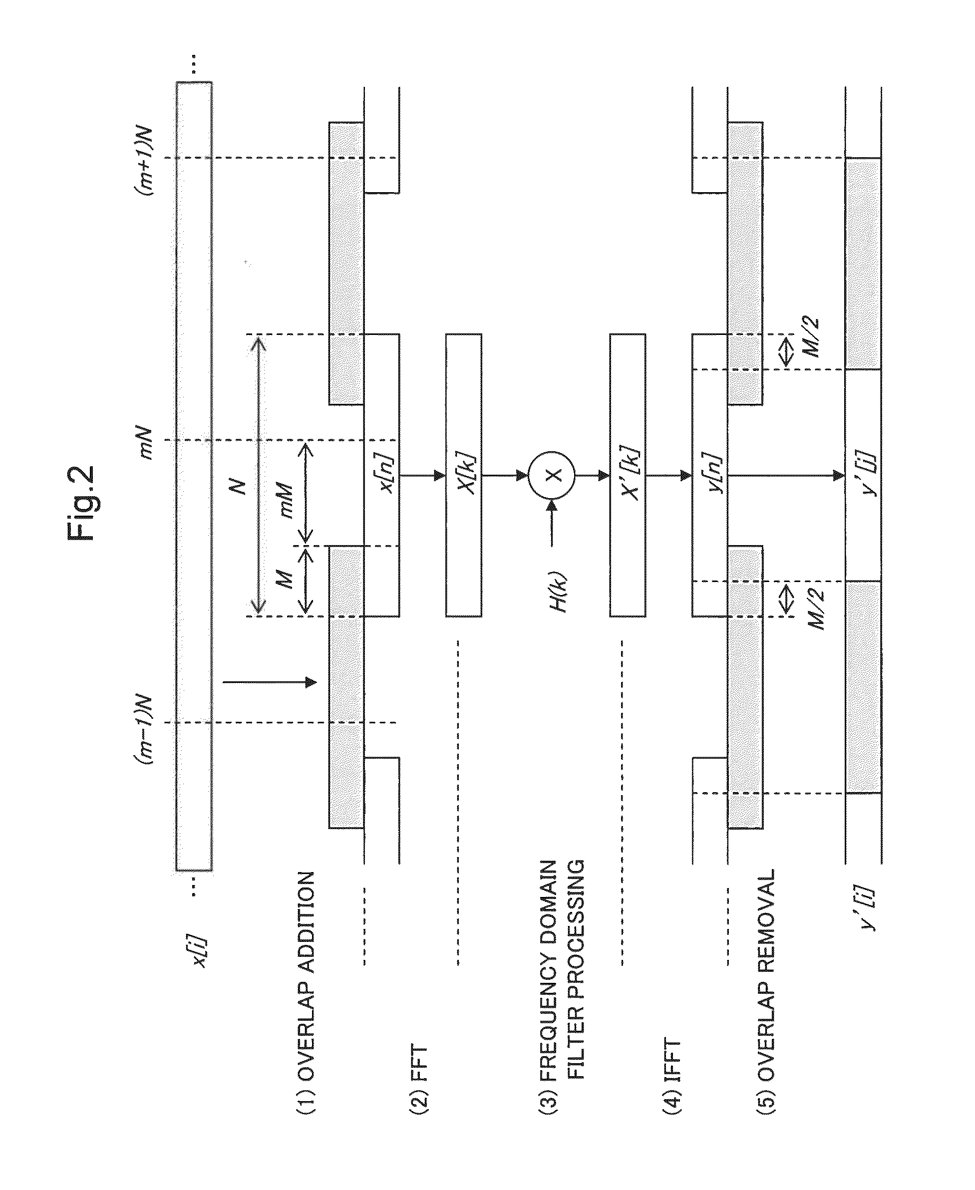
[0108]The overlap addition means 1001 generates a block including N data from an input data in the time domain by overlapping only M data with the previous block. Further, N and M are positive integers.

[0109]The FFT means 1002 transforms a block, which is generated by the overlap addition means 1001, by FFT processing to a block in the frequency domain.

[0110]The filter computation means 1003 performs filter processing to the block, in the frequency domain, transformed by the FFT means 1002.

[0111]The IFFT means 1004 transforms the block, to which the filter computation means 1003 performed the filter...


PUM


Abstract

[Objective]
To provide a digital filter circuit and a digital filter control method which are capable of reducing circuit scale and power consumption for filter processing in a frequency domain such as an overlap FDE method.
[Solution]
A digital filter circuit according to the present invention includes: an overlap addition means for giving an overlap of M data (M is a positive integer) between the block and the previous block; an FFT processing means for transforming the generated block by FFT processing; a filter computation means for performing filter processing to the transformed block; an IFFT means for transforming the block, which the filter processing was performed to, by IFFT processing; an overlap removal means for removing M units of data from both ends of the transformed block; and a clock generation means for setting the frequency of a filter processing clock signal based on a value of M, wherein the filter processing clock signal drives the data output unit of the overlap addition means, the FFT means, the filter computation means, the IFFT means, and the input unit of the overlap removal means.

Description

TECHNICAL FIELD[0001]The present invention relates to an arithmetic processing circuit in digital signal processing and relates to a digital filter circuit and a digital filter control method in particular.BACKGROUND ART[0002]As a technology which compensates for waveform distortion in signal transmission in wireless communication and cable communication, a frequency domain equalization (FDE) technology is known. In FDE, first, a signal data in the time domain is converted to data in the frequency domain by Fast Fourier Transform (FFT). Then filter processing for equalization is performed and the signal data in the frequency domain is reconverted to the signal data in the time domain by Inverse FFT (IFFT). In FDE, by the above-mentioned processing, the waveform distortion of the signal is compensated for.[0003]Meanwhile, in FFT, it is assumed that a signal repeats periodically, it is a problem that a computation distortion occurs in a signal around both ends of a processing block of...

Claims


Application Information

Patent Timeline
Patent Type & Authority Applications(United States)
IPC IPC(8): H03H17/02
CPCH03H17/0248H03H17/0213H03H2017/0245
Inventor SHIBAYAMA, ATSUFUMI
Owner NEC CORP
Why Eureka
Try Eureka