Vibrator drive circuit

a technology of vibrators and drives, applied in the direction of instruments, devices using electric/magnetic means, acceleration measurement using interia forces, etc., can solve the problem of difficult dynamically couple a plurality of vibrators to cause resonance frequencies to coincide with each other, and achieve the effect of reducing circuit scale and power consumption

Active Publication Date: 2016-12-29
MURATA MFG CO LTD
View PDF2 Cites 5 Cited by
  • Summary
  • Abstract
  • Description
  • Claims
  • Application Information

AI Technical Summary

Benefits of technology

[0014]According to the preferred aspect of the present invention, the phase detector is configured to adjust an output voltage in accordance with the phase difference between the vibration waveform of the vibrator and the reference signal to change electrostatic force in the capacitor for controlling the phase difference to be 90 degrees. Accordingly, the resonance frequency of the vibrator can be caused to coincide with the frequency of the reference signal. Consequently, the resonance frequencies of the plurality of vibrators can be caused to coincide with the frequency of the reference signal, thereby allowing sharing of at least a part of the circuit configuration for driving a plurality of vibrators, so that the circuit scale and the power consumption can be reduced.

Problems solved by technology

It is extremely difficult to dynamically couple a plurality of vibrators to cause resonance frequencies to coincide with one another, as in the conventional technique disclosed in the above-mentioned PTD 2.

Method used


Image

  • Vibrator drive circuit
  • Vibrator drive circuit
  • Vibrator drive circuit

Examples


Embodiment Construction

[0027]Preferable embodiments according to the present invention will be hereinafter described with reference to the accompanying drawings. In the following description of the embodiments, the same components are designated by the same reference characters, and the description thereof will not be repeated.

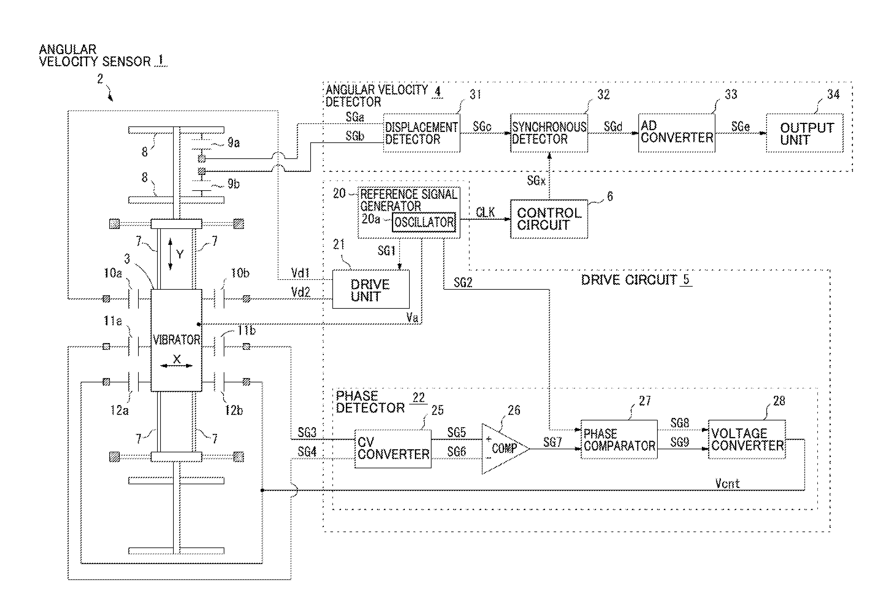
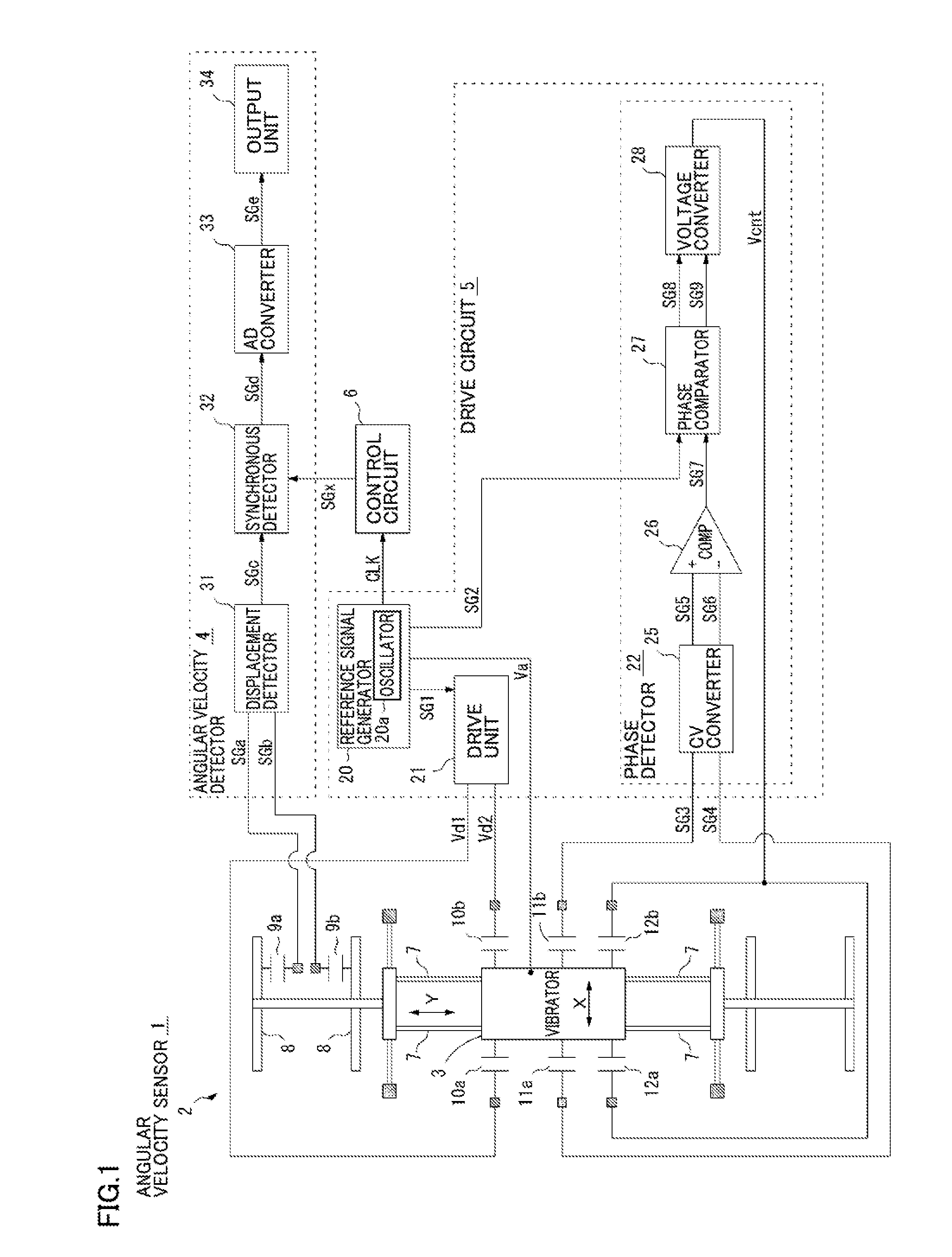
[0028]FIG. 1 is a diagram showing an angular velocity sensor 1 in accordance with a first embodiment of the present embodiment. This angular velocity sensor 1 serves as a sensor mounted, for example, in an information processing terminal such as a smart phone or a tablet terminal. As shown in FIG. 1, angular velocity sensor 1 includes a vibrator unit 2, an angular velocity detection circuit 4, a vibrator drive circuit (which will be hereinafter simply referred to as a “drive circuit”) 5, and a control circuit 6.

[0029]Vibrator unit 2 is preferably formed of an MEMS (Micro Electro Mechanical Systems) structure and includes a vibrator mass 3 that can be displaced in the X-axis and Y-ax...


PUM


Abstract

A vibrator drive circuit is configured to drive a vibrator mass 3 in a prescribed vibration direction. The vibrator drive circuit includes a drive unit configured to drive a vibrator based on a reference signal SG1 of a predetermined frequency to cause the vibrator to vibrate in a vibration direction, a phase detector configured to detect a vibration waveform of the vibrator in the vibration direction and to output an output voltage Vcnt in accordance with a phase difference between reference signal SG1 and a vibration waveform thereof, and two capacitors each formed of a movable electrode provided in the vibrator and a fixed electrode provided to face the movable electrode, the output voltage Vcnt being applied to the fixed electrode. The phase detector is configured to adjust the output voltage Vcnt in accordance with the phase difference, thereby changing electrostatic force in each of the capacitors for controlling the phase difference to be 90 degrees.

Description

CROSS REFERENCE TO RELATED APPLICATIONS[0001]The present application is a continuation of International application No. PCT / JP2015 / 056902, filed Mar. 10, 2015, which claims priority to Japanese Patent Application No. 2014-061258, filed Mar. 25, 2014, the entire contents of each of which are incorporated herein by reference.TECHNICAL FIELD[0002]The present invention relates to a vibrator drive circuit included in a vibration-type angular velocity sensor and causing a vibrator to vibrate in a prescribed vibration direction.BACKGROUND ART[0003]A vibration-type angular velocity sensor serves as a sensor for measuring the magnitude of the angular velocity by causing a vibrator to vibrate at a predetermined frequency in a prescribed vibration direction, thereby generating Coriolis force in accordance with the angular velocity acting from the outside, and detecting the displacement amount of the vibrator caused by the Coriolis force in the direction orthogonal to the vibration direction. T...

Claims


Application Information

Patent Timeline
Patent Type & Authority Applications(United States)
IPC IPC(8): G01C19/5726
CPCG01C19/5726
Inventor ONO, HIDEKAZUTSUJI, NOBUAKIOKAMI, TSUYOSHIMIZOTA, TAKASHI
Owner MURATA MFG CO LTD
Why Eureka
Try Eureka