Feeding Structure for Dual Slot Microwave Ablation Probe

a dual-slot microwave ablation and feeding structure technology, applied in the field of microwave antennas, can solve problems such as degrading this desirable sar pattern, and achieve the effect of improving the iso-contour of the dual-slot antenna

Active Publication Date: 2013-10-10
WISCONSIN ALUMNI RES FOUND
View PDF1 Cites 9 Cited by
  • Summary
  • Abstract
  • Description
  • Claims
  • Application Information

AI Technical Summary

Benefits of technology

The present invention is a microwave ablation probe with a dual slot antenna design that has a feeding structure to improve its performance. This feeding structure helps to balance the energy emitted from the dual slots of the antenna and create a more uniform heating pattern. This design can make the microwave ablation probe more effective and safer for use in clinical settings.

Problems solved by technology

The patent text describes a problem with current microwave probes used for tissue ablation. The problem is that the heating pattern produced by the microwave energy is not always ideal, with the shaft of the probe often being heated more than the tip. This can lead to unnecessary damage to healthy tissue and limits the effectiveness of treatment. The patent aims to address this problem by designing a new microwave antenna that produces a more concentrated heating pattern at the boundary of the ablation region. However, this design is currently not optimal, so the patent proposes modifications to improve its performance.

Method used


Image

  • Feeding Structure for Dual Slot Microwave Ablation Probe
  • Feeding Structure for Dual Slot Microwave Ablation Probe
  • Feeding Structure for Dual Slot Microwave Ablation Probe

Examples


Embodiment Construction

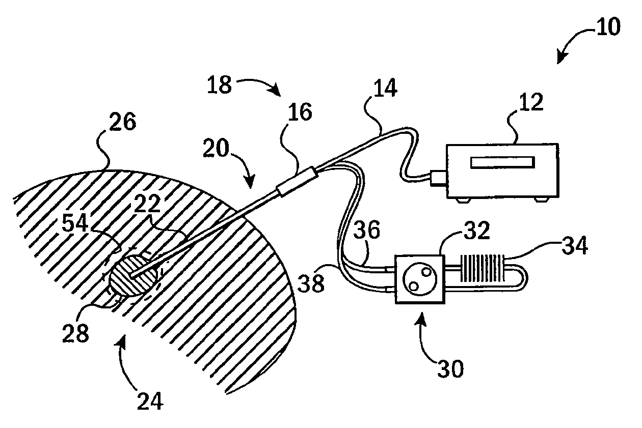
[0040]Referring now to FIG. 1, a microwave ablation system 10 suitable for use with the probe of the present invention may provide a microwave source 12 generating a microwave electrical signal in the microwave region (typically from 1 to 3 GHz), for example at substantially 2.45 GHz for the embodiment described below. A microwave signal from the microwave source 12 may be conducted along a flexible coaxial cable 14 to a connector 16 on a proximal end 18 of a microwave ablation probe 20.

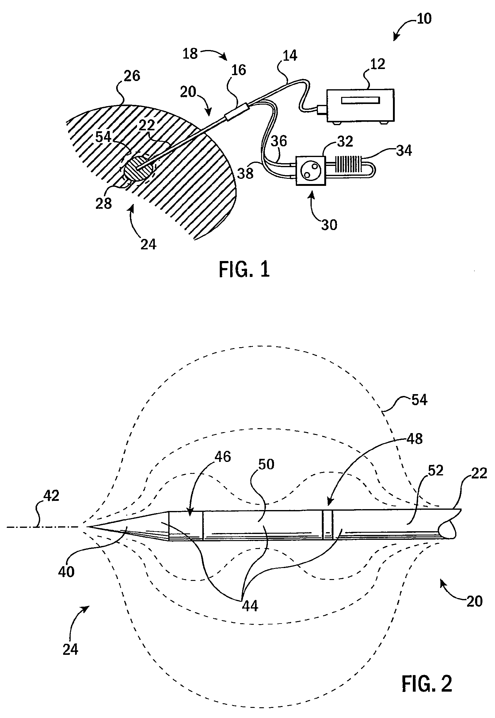
[0041]The probe 20 provides a substantially rigid elongate shaft 22 whose distal end 24 may be inserted percutaneously to the skin of the patient 26 so that the distal end 24 lies within a tumor 28. It will be appreciated that the structure of the probe 20 may also be used in open surgery without percutaneous insertion.

[0042]An external cooling system 30 may connect with the probe 20 and provide for a pump 32 and heat exchanger 34 communicating via a flexible hose 36 with the connector 16 providing a...


PUM


Abstract

A dual slot microwave probe for tissue ablation provides axially spaced slots producing an improved heating pattern with reduced axial extent. Degradation in this heating pattern caused by the addition of ceramic support elements and/or fluid cooling is realized through a feeding structure delivering separate sources of microwave energy to the different slots of the probe aligned with the slots of the probe.

Description


Claims


Application Information

Patent Timeline
Owner WISCONSIN ALUMNI RES FOUND
Why Eureka
Try Eureka