Delivery System for Fracture Applications

a delivery system and fracturing technology, applied in mechanical equipment, sealing/packing, and borehole/well accessories, etc., can solve the problems of consuming a considerable amount of time and manpower, affecting the operation of the system, and the management of the number of trucks, pumps, etc., to achieve the effect of reducing the number of operators and reducing the number of fractures

Active Publication Date: 2013-10-31
VAULT PRESSURE CONTROL LLC
View PDF4 Cites 223 Cited by
  • Summary
  • Abstract
  • Description
  • Claims
  • Application Information

AI Technical Summary

Benefits of technology

[0011]In some embodiments, the supply of slurry is in fluid communication with the water supply. In some embodiments, the water pipeline and the slurry pipeline are in parallel with the high-pressure pipeline. In some embodiments, the delivery system further includes a frac skid adjacent the wellhead, and the frac skid includes at least one frac manifold in fluid communication with the high-pressure pipeline. In some embodiments, the first and second pump skids each include a jack operable to adjust an elevation of the respective pump skid, and in some embodiments, the delivery system further includes an elevation measurement device, and the first and second pump skids each include a leveling target thereon providing a reference for the elevation measurement device.
[0012]According to another aspect of the disclosure, a collection manifold for delivering fluid to a wellhead includes a first low-pressure pipeline comprising an end in fluid communication with a source of fluid and a high-pressure pipeline having an end in fluid communication with the wellhead. A first pump skid supports a first distribution junction and a first exit junction thereon. The first low-pressure pipeline connects to an inlet of a first pump through the first distribution junction and the high-pressure pipeline connects to an outlet of the first pump through the first exit junction. A second pump skid is disposed remotely from the first pump skid. The second pump skid supports a second distribution junction and a second exit junction thereon, and the first low-pressure pipeline connects to an inlet of a second pump through the second distribution junction and the high-pressure pipeline connects to an outlet of the second pump through the second exit junction.
[0013]In some embodiments, the high-pressure pipeline connects to a plurality of pumps through a plurality of inlets defined in the first exit junction, and the plurality of inlets are arranged on two opposing sides of the first pump skid. In some embodiments, the first and second exit junctions are fluidly coupled in series to one another. In some embodiments, the delivery system further includes a bypass high-pressure pipeline in fluid communication with the first and second exit junctions.
[0014]In some embodiments, the first low-pressure pipeline is a slurry pipeline in fluid communication with a source of slurry. In some embodiments, the collection manifold further includes a second low pressure pipeline, and the second low-pressure pipeline is a water pipeline in fluid communication with a water source and in fluid communication with the high-pressure pipeline through a third pump.
[0015]In some embodiments, the collection manifold further includes a safety blanket positioned between the first and second pump skids. In some embodiments, the high-pressure pipeline includes first and second high-pressure pipe segments coupled to one another by a hub connector having a seal ring disposed longitudinally between the first and second pipe segments and a clamping ring with two opposing members operable to urge the first and second pipe segments longitudinally toward one another in response to movement of the two opposing members toward one another in a lateral direction.
[0016]According to another aspect of the disclosure, a method of assembling a manifold for delivering fluid to a wellhead includes (i) assembling a distribution junction and an exit junction to each of a plurality of bases to form a plurality of pump skids, (ii) arranging the plurality of pump skids at a well site, (iii) fluidly coupling a first low-pressure pipeline to at least one the distribution junctions disposed on the plurality of pump skids, wherein the first low pressure pipeline extends to a fluid source, and (iv) fluidly coupling a high-pressure pipeline to each of the exit junctions disposed on the plurality of pump skids, wherein the high-pressure pipeline extends to the wellhead.

Problems solved by technology

The management of the number of trucks, pumps, containers, pipelines, and other equipment for a fracturing system presents significant challenges to an operator.
These connections and disconnections consume a considerable amount of time and manpower.

Method used


Image

  • Delivery System for Fracture Applications
  • Delivery System for Fracture Applications
  • Delivery System for Fracture Applications

Examples


Embodiment Construction

[0027]The present invention will now be described more fully hereinafter with reference to the accompanying drawings, which illustrate various embodiments of the invention. This invention, however, may be embodied in many different forms and should not be construed as limited to the illustrated embodiments set forth herein; rather, these embodiments are provided so that this disclosure will be thorough and complete, and will fully convey the scope of the invention to those skilled in the art.

1. Modularity and Isolation

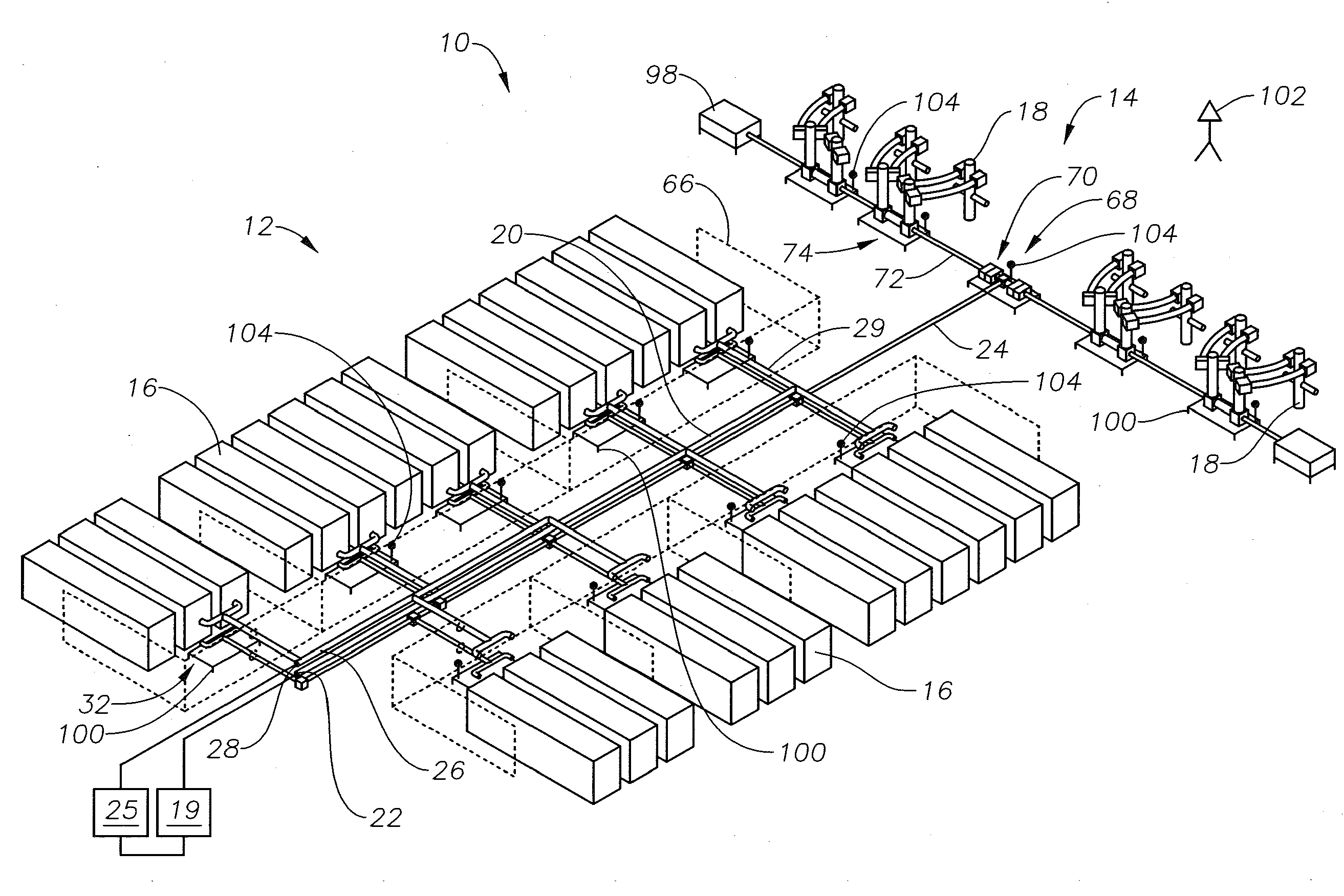
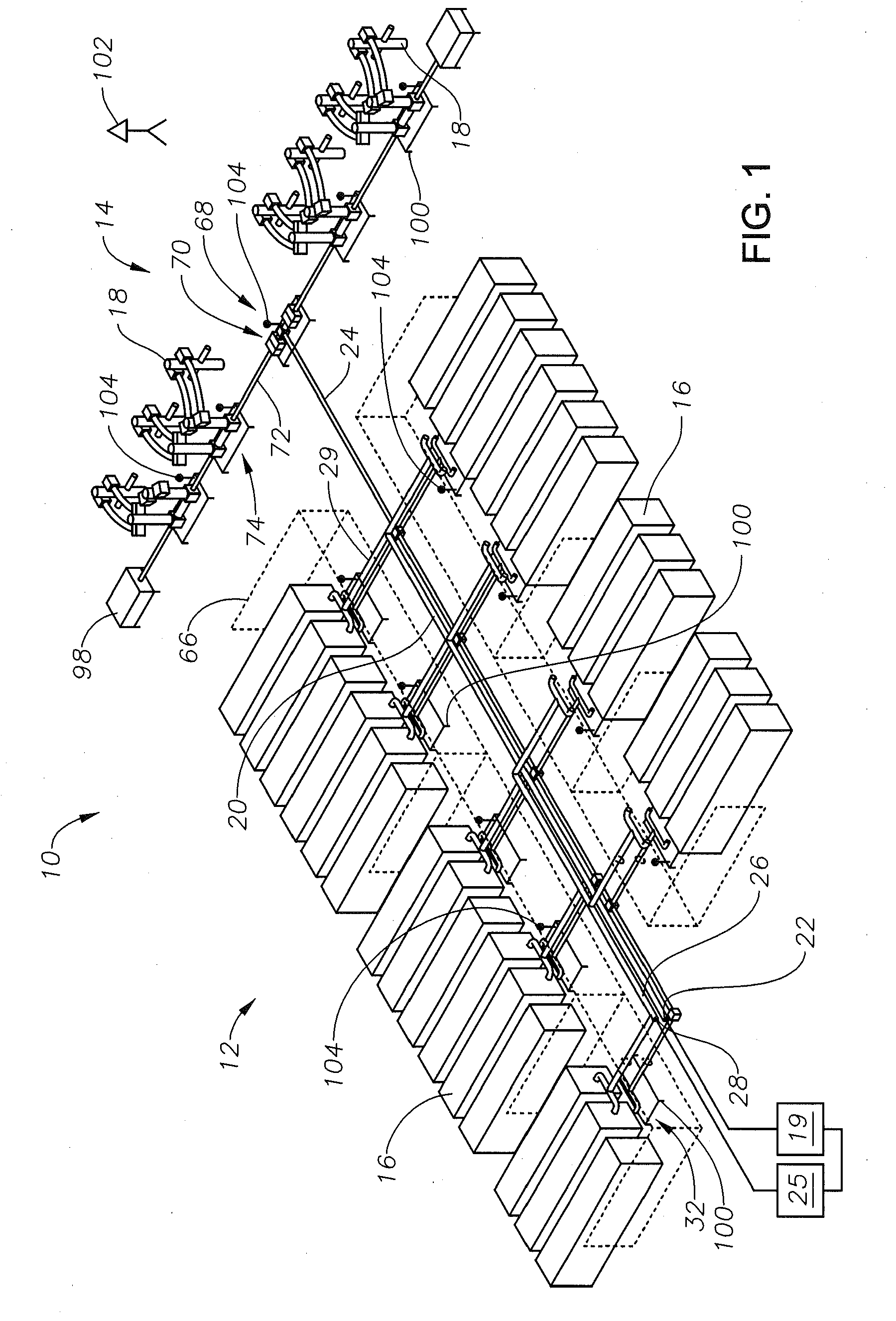
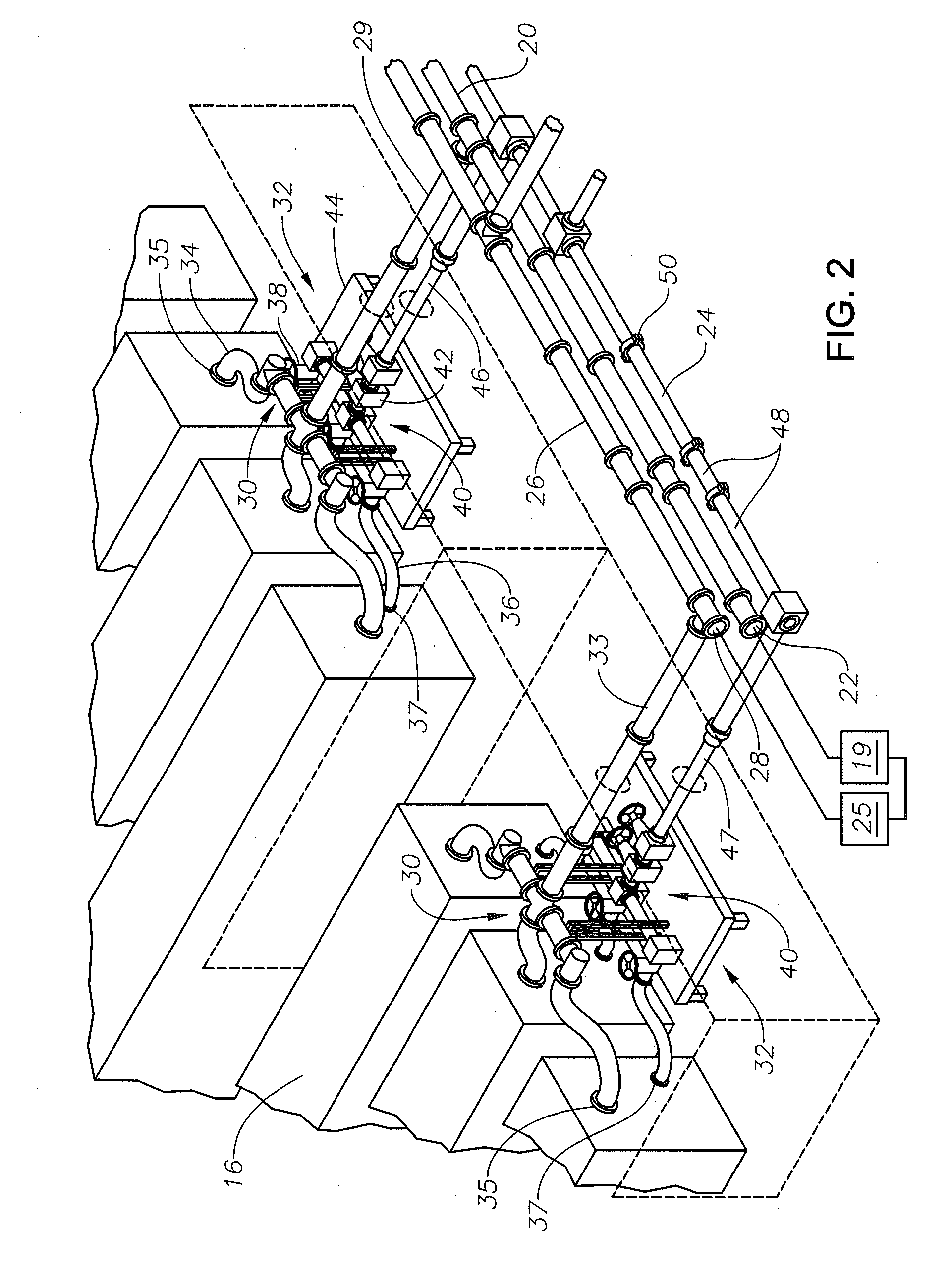
[0028]Referring to FIG. 1, shown in an overhead perspective view is an example of a delivery system 10 for use in delivering fluids under pressure includes a collection manifold 12 and a delivery section 14. This delivery system 10 may be used, for example, for delivering fracturing fluids through pump trucks 16 to wellheads 18. The fracturing fluids may be made up of sand, water and other additives, which is mixed in blenders 19 to create a low-pressure slurry. This s...


PUM


Abstract

Described herein is a modular, adjustable system for distributing fluids to one or more wellbores. The system is readily configured and assembled at a well site, and allows for one portion of the system to be isolated for service or repair while the remainder of the system continues to operate. The system includes a plurality of pump skids having both a distribution junction in fluid communication with inlets to of plurality of pump trucks and an exit junction in fluid communication with outlets of the plurality of pump trucks.

Description

CROSS-REFERENCE TO RELATED APPLICATIONS[0001]This application claims priority to and the benefit of co-pending U.S. Provisional Application 61 / 638,818, filed Apr. 26, 2012, the full disclosure of which is hereby incorporated by reference herein for all purposes.BACKGROUND OF THE INVENTION[0002]1. Field of the Invention[0003]Embodiments of the present invention relate in general to fluid delivery systems and in particular to manifolds for delivering fluids under pressure.[0004]2. Description of the Related Art[0005]Often in oilfield operations, fluids are pumped into a wellbore extending through a geologic formation. Hydraulic fracturing is an example of an oilfield operation in which fluids are pumped into a wellbore at a sufficient pressure to fracture the geologic formation. Fracturing the geologic formation provides a conductive path for hydrocarbons captured in the geologic formation to reach the wellbore, and thereby facilitates recovery of the hydrocarbons through the wellbore...

Claims


Application Information

Patent Timeline
Patent Type & Authority Applications(United States)
IPC IPC(8): E21B43/26
CPCE21B43/26E21B33/03F16L23/08E21B43/2607
Inventor KAJARIA, SAURABHNGUYEN, KHANG
Owner VAULT PRESSURE CONTROL LLC
Why Eureka
Try Eureka