Vacuum cleaner

a vacuum cleaner and travel head technology, applied in the field of vacuum cleaners, can solve the problems of dragging dirt and debris from the vacuum cleaner, falling back or being brushed back onto the surface, and large debris can be pushed along by the leading edge of the travelling head, so as to achieve the effect of low power consumption or battery-powered vacuum cleaners

Active Publication Date: 2013-11-07
GREY TECHNOLOGY
View PDF2 Cites 44 Cited by
  • Summary
  • Abstract
  • Description
  • Claims
  • Application Information

AI Technical Summary

Benefits of technology

[0016]The present invention seeks to provide an improved vacuum cleaner which h...

Problems solved by technology

A disadvantage of traditional vacuum cleaners is that some of the dirt and debris which has been dislodged by the rotating brush falls back or is brushed back onto the surface before it is gathered by the air flow.
A further disadvantage is that larger debris can be pushed along by the leading edge of the travelling head rather than being collected.
This disadvantage is caused by the close proximity of the bottom of the leading edge to the surface being cleaned.
A further disadvantage is that larger debris that is collected can lodge in the ducts and block the vacuum cleaner.
As impellers are typically 10 to 40% efficient in use and air is not particularly good at dislodging dust, dirt and debris, this is a relatively inefficient method of cleaning.
However, as it is air flow rather than suction which dislodges dirt and debris, such vacuum cleaners generally do not achieve improved dirt and debris collection efficiency.
Battery-powered vacuum cleaners employing this tra...

Method used


Image

  • Vacuum cleaner
  • Vacuum cleaner
  • Vacuum cleaner

Examples


Embodiment Construction

[0049]The invention will now be described in more detail, by way of example, with reference to the accompanying drawings, in which:

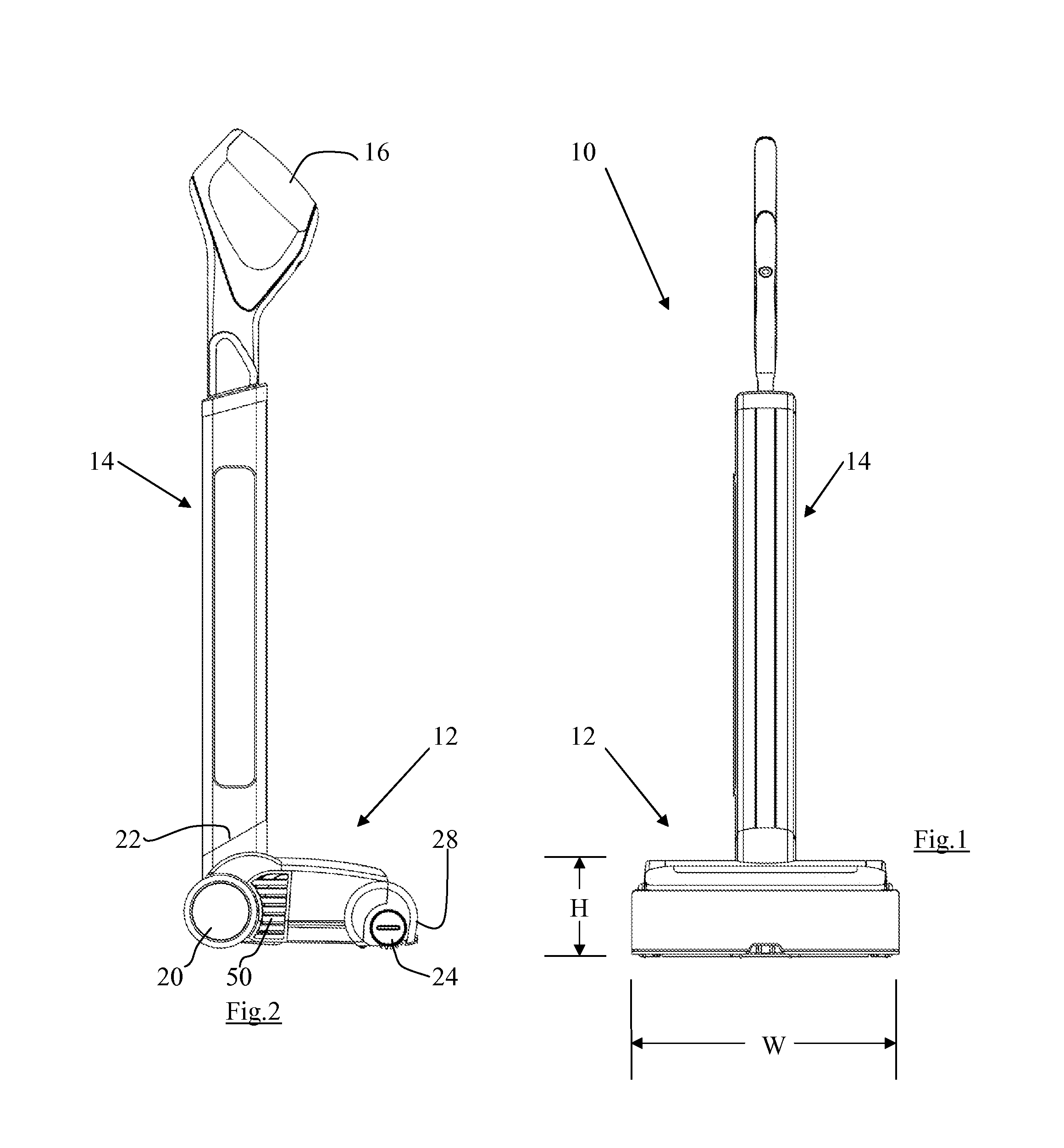
[0050]FIG. 1 shows a front view of a vacuum cleaner according to the present invention;

[0051]FIG. 2 shows a side view of the vacuum cleaner of FIG. 1;

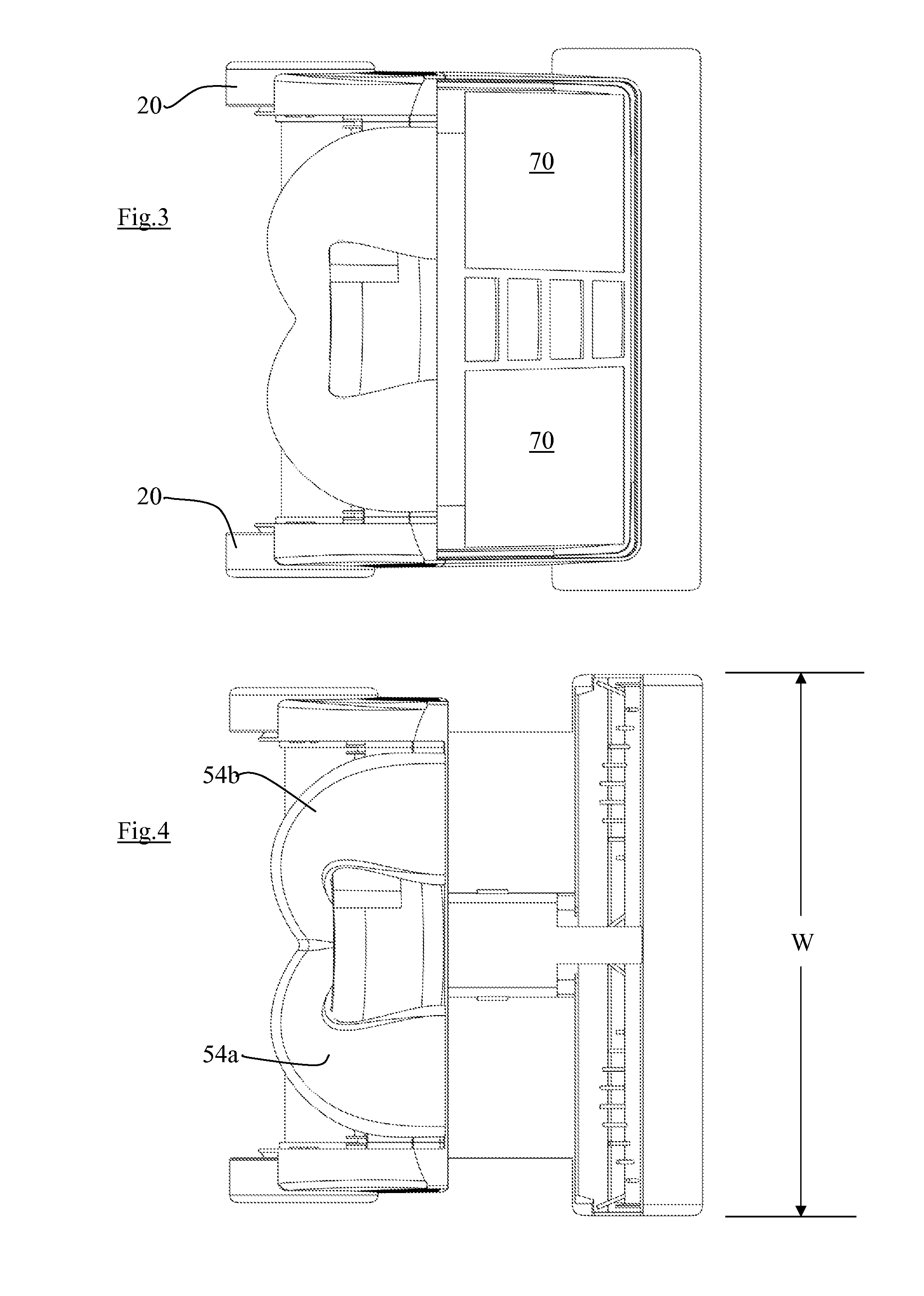
[0052]FIG. 3 shows a plan view of the travelling head of the vacuum cleaner (but with the filter cover removed);

[0053]FIG. 4 shows a view as FIG. 3, but with the dirt-collection chamber removed;

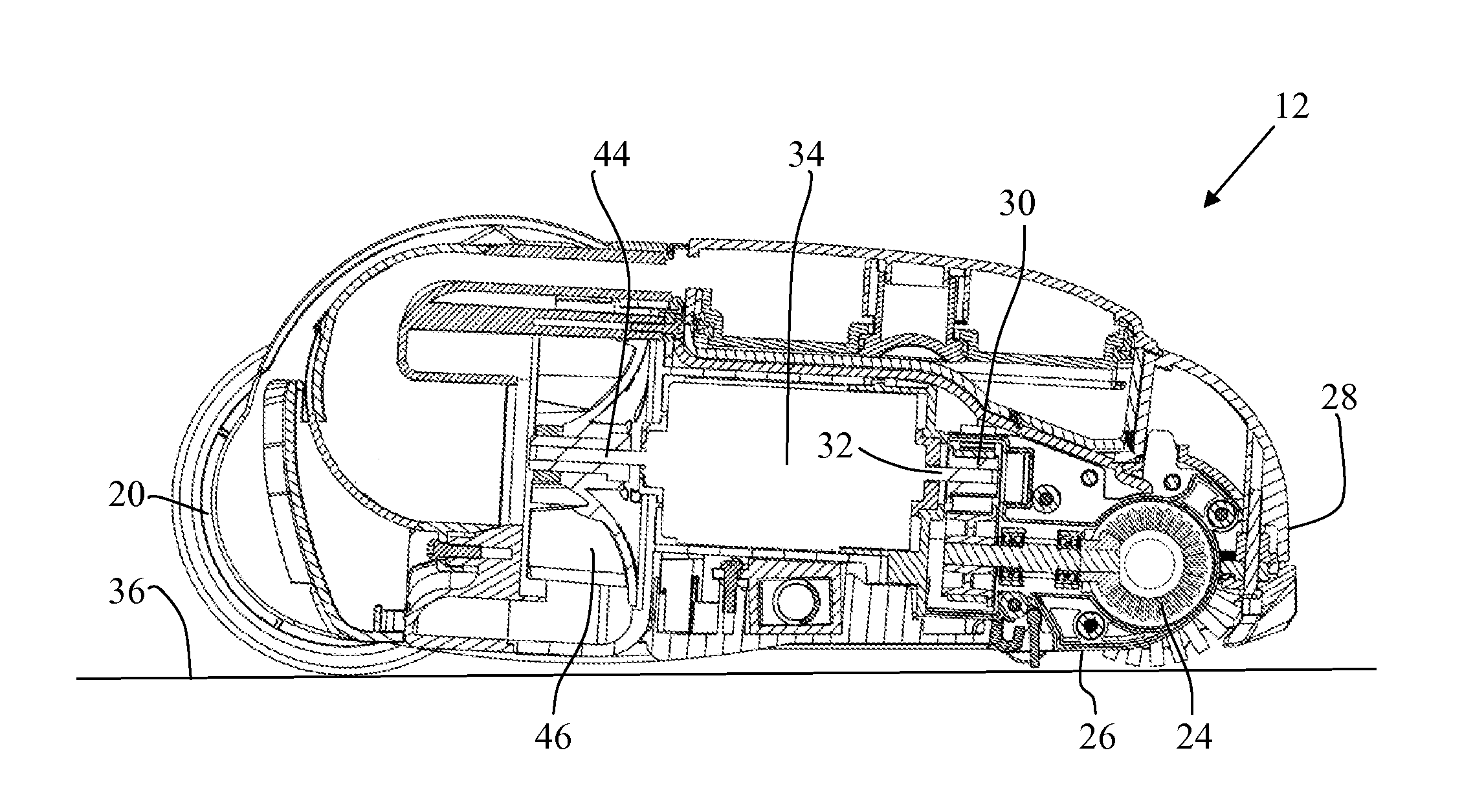
[0054]FIG. 5 shows a longitudinal sectional view along the approximate centre line of the vacuum cleaner;

[0055]FIG. 6 shows a longitudinal sectional view similar to that of FIG. 5, with the portion to the left of the dashed line being along the approximate centre line and the portion to the right of the dashed line being offset from the centre line;

[0056]FIG. 7 shows an exploded view of an alternative embodiment of dirt-collection chamber;

[0057]FIG. 8 shows the rotatable brush, motor and impeller of the vacuum cleane...


PUM


Abstract

This invention relates to a vacuum cleaner (10), and in particular a vacuum cleaner (10) having a rotatable brush (24). The vacuum cleaner (10) has a travelling head (12) adapted to be moved across a surface to be cleaned, the travelling head (12) having a leading end (28) and a trailing end. The travelling head (12) has a rotatable brush (24), the rotatable brush (34) being located in a brush chamber (23) at the leading end of the travelling head (12), the brush chamber (34) having an opening (26) through which a part of the rotatable brush (24) projects, the opening (26) and the rotatable brush (24) spanning substantially the full width of the travelling head (12). The travelling head (12) also has an impeller (46), and a motor (34) for driving the rotatable brush (34) and the impeller (46). The travelling head (12) has a removable dirt-collection chamber (42) spanning substantially the full width of the travelling head, and a filter means (52) located between the dirt-collection chamber (42) and the impeller (46), the filter means (52) also spanning substantially the full width of the travelling head.

Description

FIELD OF THE INVENTION[0001]This invention relates to a vacuum cleaner, and in particular a battery-powered vacuum cleaner including a rotatable brush.[0002]In the following description, directional and orientational terms such as “top”, “bottom” etc. refer to the vacuum cleaner in its normal orientation of use upon a substantially horizontal surface 36, as shown for example in FIGS. 1, 2, 5 and 6. It will be understood, however, that the vacuum cleaner can be used in other orientations.[0003]BACKGROUND TO THE INVENTION[0004]Vacuum cleaners have a motor which typically drives an impeller to create a flow of air. The travelling head of the vacuum cleaner has an opening in its bottom wall through which air can enter the travelling head, the air carrying dirt and debris into the travelling head. It is arranged that the air transports the dirt and debris by way of ducts within the travelling head, the ducts typically having a cross-sectional area measuring around 7 to 10 cm2. The dirt a...

Claims


Application Information

Patent Timeline
IPC IPC(8): A47L5/30A47L9/14A47L9/12
CPCA47L5/30A47L9/12A47L9/1409A47L9/0411A47L9/122A47L9/22A47L9/28A47L9/325A47L7/02A47L9/04A47L11/24A47L11/32
Inventor GREY, NICHOLAS GERALD
Owner GREY TECHNOLOGY
Why Eureka
Try Eureka