Gear motor having safety mechanism

Active Publication Date: 2013-12-12
TIMOTION TECH CO LTD
View PDF34 Cites 9 Cited by
  • Summary
  • Abstract
  • Description
  • Claims
  • Application Information

AI Technical Summary

Benefits of technology

[0011]The clockwise or counterclockwise rotation of the lead screw rod will causes the nut to move linearly, so that the motor body stops running when the nut contacts the touch switch. In this way, the contact position between the touch switch and the nut can be used to control the maximum number of rotations of the lead screw rod. In this way, the number of rotations of the lead screw rod can be prevented from exceeding a predetermined value of a user, thereby increasing the safety in use of the gear motor.
[0012]The rotation of an adjustable screw rod can be used to adjust the position of the contact switch relative to the nut, and further adjust the maximum number of rotations of the lead screw rod. On the other hand, the nut and a portion of the touch switch are exposed to the outside of the base, so that they can be inspected and adjusted easily by the user and even a fine adjustment is possible.
[0013]The gear motor of the present invention is additionally mounted with a driven mechanism, so that the driving mechan

Problems solved by technology

However, in practice, the above linear actuator still has following problems.
Thus, the manufacturers in this field have to prepare var

Method used


Image

  • Gear motor having safety mechanism
  • Gear motor having safety mechanism
  • Gear motor having safety mechanism

Examples


Example

[0028]The detailed description and technical contents of the present invention will become apparent with the following detailed description accompanied with related drawings. It is noteworthy to point out that the drawings is provided for the illustration purpose only, but not intended for limiting the scope of the present invention.

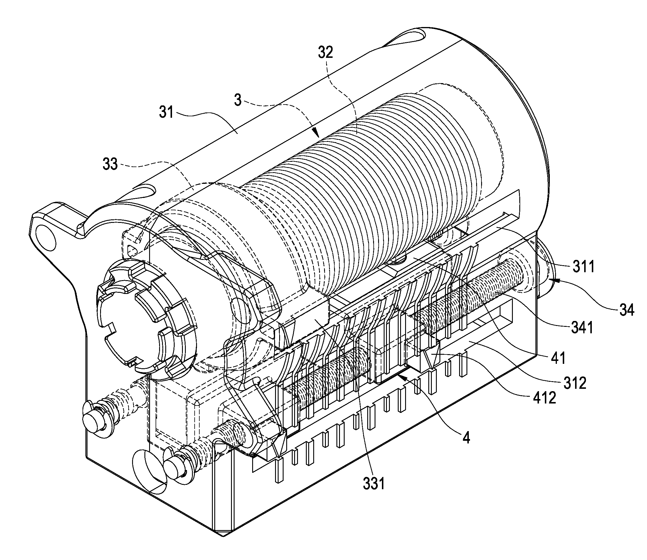
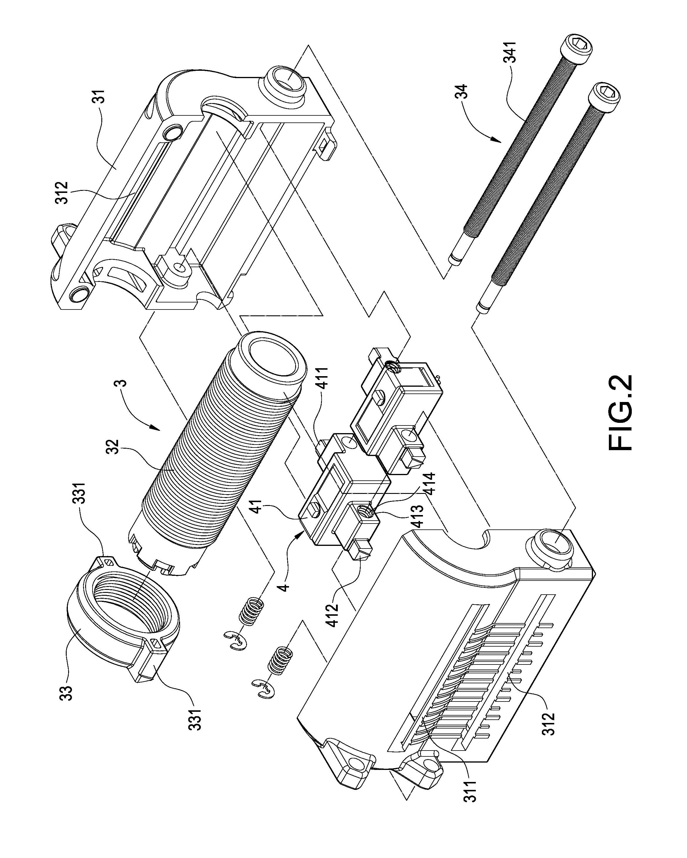
[0029]Please refer to FIGS. 2 to 5. The present invention provides a gear motor having a safety mechanism, which includes a motor body 1, a speed reduction mechanism 2, a transmission mechanism 3 and a touch switch 4.

[0030]The speed reduction mechanism 2 comprises a casing 21, a worm 22, and a worm wheel 23. The casing 21 covers the worm 22 and the worm wheel 23. The worm 22 extends from the motor body 1. The worm wheel 23 is positioned to correspond to the worm 22 and drivingly engaged therewith.

[0031]The transmission mechanism 3 comprises a base 31 fixed to the speed reduction mechanism 2, a lead screw rod 32 pivotally connected to the base 31 and rota...


PUM


Abstract

A gear motor having a safety mechanism includes a motor body, a speed reduction mechanism, a transmission mechanism, and a touch switch. The speed reduction mechanism includes a worm and a worm wheel drivingly engaged with the worm. The transmission mechanism includes a base fixed to the speed reduction mechanism, a lead screw rod pivotally connected to the base and rotatably driven by the worm wheel, and a nut threadedly connected to the lead screw rod. The touch switch is electrically connected to the motor body and provided aside the lead screw rod, thereby stopping the motor body when the nut contacts the touch switch. Thus, the gear motor not only controls the operation of the driven mechanism, but also allows various driven mechanisms to be mounted thereon. The assembled volume of the gear motor and the driven mechanism is reduced.

Description

BACKGROUND OF THE INVENTION[0001]1. Field of the Invention[0002]The present invention relates to an actuator, and in particular to a gear motor having a safety mechanism.[0003]2. Description of Prior Art[0004]A transmission mechanism is widely used in various apparatuses such as electric sickbeds, treadmills, electric tables or the like for adjusting their height or inclination angle. The starting point and the terminal point of the stroke of the transmission mechanism are often provided with a touch switch respectively. When the transmission mechanism moves along its stroke and contacts the touch switch provided at the starting point or the terminal point, the touch switch will shut off the electricity supplied to the transmission mechanism, so that the transmission mechanism can stop operating at the terminal point or the starting point. In this way, the transmission mechanism can be prevented from idling or wearing at the starting point or the terminal point, thereby increasing t...

Claims


Application Information

Patent Timeline
IPC IPC(8): F16H25/20
CPCF16H25/2015F16H2025/2081F16H2025/2084F16H2025/209Y10T74/18688Y10T74/19702
Inventor WU, CHOU-HSIN
Owner TIMOTION TECH CO LTD
Why Eureka
Try Eureka