Safety Rotary Operator Assembly

Active Publication Date: 2010-11-25
EWAC HLDG
View PDF5 Cites 33 Cited by
  • Summary
  • Abstract
  • Description
  • Claims
  • Application Information

AI Technical Summary

Benefits of technology

[0026]In an embodiment, the assembly may comprise means for urging the grip member to a default position, such as from the second translational position towards the first translational position. In an embodiment in which a relative angular position between the spindle member and the grip member is relevant, the assembly may comprise means for urging the grip member and the spindle member to a default relative position, such as

Problems solved by technology

However, dangerous situations may arise in case the operator can be locked in a “safe” position whereas operational portions of the device are not in the corresponding desired state.
Such devices comprise a sign

Method used


Image

  • Safety Rotary Operator Assembly
  • Safety Rotary Operator Assembly
  • Safety Rotary Operator Assembly

Examples


Embodiment Construction

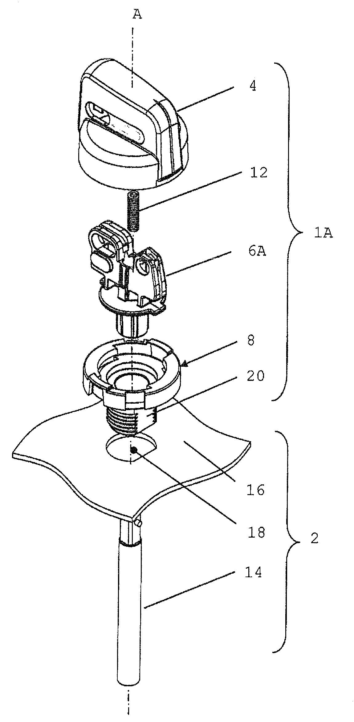
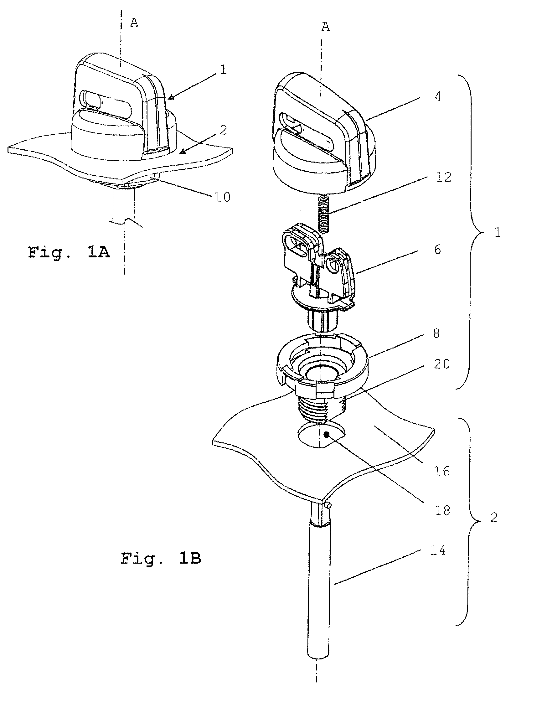
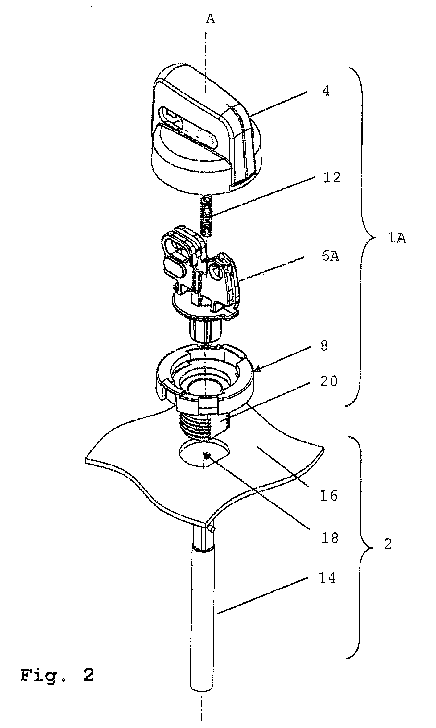
[0044]FIGS. 1A and 1B show a rotary operator assembly 1 and a fragment of a switch 2 in an assembled configuration (FIG. 1A) and in an explosion view (FIG. 1B). The rotary operator assembly 1 (or “assembly 1” for short) comprises a grip member 4, a spindle member 6, an operator body member 8 and a mounting nut 10. A compression spring 12 is arranged between the grip member 4 and the spindle member 6.

[0045]The grip member 4 is configured to receive and substantially cover the spring 12, a portion of the spindle member 6 and a portion of the operator body member 8 in the assembled configuration (FIG. 1A) providing a generally closed assembly 1.

[0046]The switch 2 comprises a rotary spindle 14 and a housing 16.

[0047]The spindle 14 is rotatable with respect to the housing 16 about an axis of rotation A. The grip member 4 and the spindle member 6 are generally rotatable with respect to the operator body member 8 about the axis of rotation A (see below).

[0048]The operator body member 8 is ...


PUM

PropertyMeasurementUnit
Currentaaaaaaaaaa
Currentaaaaaaaaaa

Abstract

A rotary operator assembly (1A) includes a grip member (4), a spindle member (6A), and an operator body member (8). The spindle member (6A) is attached to the operator body member (8), being rotatable with respect to the operator body member (8) about an operative axis of rotation (A). The grip member (4) is movably coupled to the spindle member (6A) and the operator body member (8) and is translatable between a first translational position and a second translational position with respect to the operator body member (8). The grip member (4) and the operator body member (8) include cooperating means for blocking rotation of the grip member (4) with respect to the operator body member (8) about the operative axis of rotation in the first position and for allowing rotation of the grip member (4) with respect to the operator body member (8) about the operative axis of rotation in the second position from a first angular position to a second angular position. The grip member (4) is configured to operably couple with the spindle member (6A) in at least the second translational position, and the grip member (4) comprises at least one portion cooperating with at least one portion of the spindle member (6A) for preventing translation of the grip member (4) between the first translational position and the second translational position in the first angular position.

Description

FIELD OF THE DISCLOSURE[0001]The present disclosure relates to the field of rotary operators, in particular rotary operators comprising safety features against unintended operation.BACKGROUND OF THE DISCLOSURE[0002]Rotary operable devices are well known, as are rotary operators for operating such devices are well known. Examples are rotary switches and valves comprising a manually operable rotary operator such as a handle grip, a knob or a lever. A particular class of rotary operators is formed by safety rotary operators in which the device may be blocked from unintended operation by locking the operator in a particular position (safe position) corresponding to a particular state of the device, e.g. an “off” state.[0003]However, dangerous situations may arise in case the operator can be locked in a “safe” position whereas operational portions of the device are not in the corresponding desired state. For instance, in some rotary electrical switches having stationary electrical contac...

Claims


Application Information

Patent Timeline
IPC IPC(8): H01H19/02H01H65/00
CPCG05G1/08G05G5/005H01H3/20H01H71/501Y10T29/49826H01H2009/288B60K37/06B60K2350/102Y10T74/20636H01H71/56B60K2370/126B60K2370/158
Inventor REDDERING, MAARTEN WILLEMMAGERMANS, MARCEL P.
Owner EWAC HLDG
Why Eureka
Try Eureka