Decay heat removal system comprising heat pipe heat exchanger

Inactive Publication Date: 2009-10-01
KOREA ATOMIC ENERGY RES INST +1
View PDF7 Cites 21 Cited by
  • Summary
  • Abstract
  • Description
  • Claims
  • Application Information

AI Technical Summary

Benefits of technology

[0023]Accordingly, the present invention has been made to solve the above problems, and an object of the present invention is to provide a decay heat removal

Problems solved by technology

However, the decay heat removal system 10 is problematic in that, although its heat removal function is performed by just the natural circulation of a heat transfer medium (sodium), the dampers 18 and valves 19 are

Method used


Image

  • Decay heat removal system comprising heat pipe heat exchanger
  • Decay heat removal system comprising heat pipe heat exchanger
  • Decay heat removal system comprising heat pipe heat exchanger

Examples


Example

[0041]Hereinafter, preferred embodiments of the present invention will be described in detail with reference to the attached drawings.

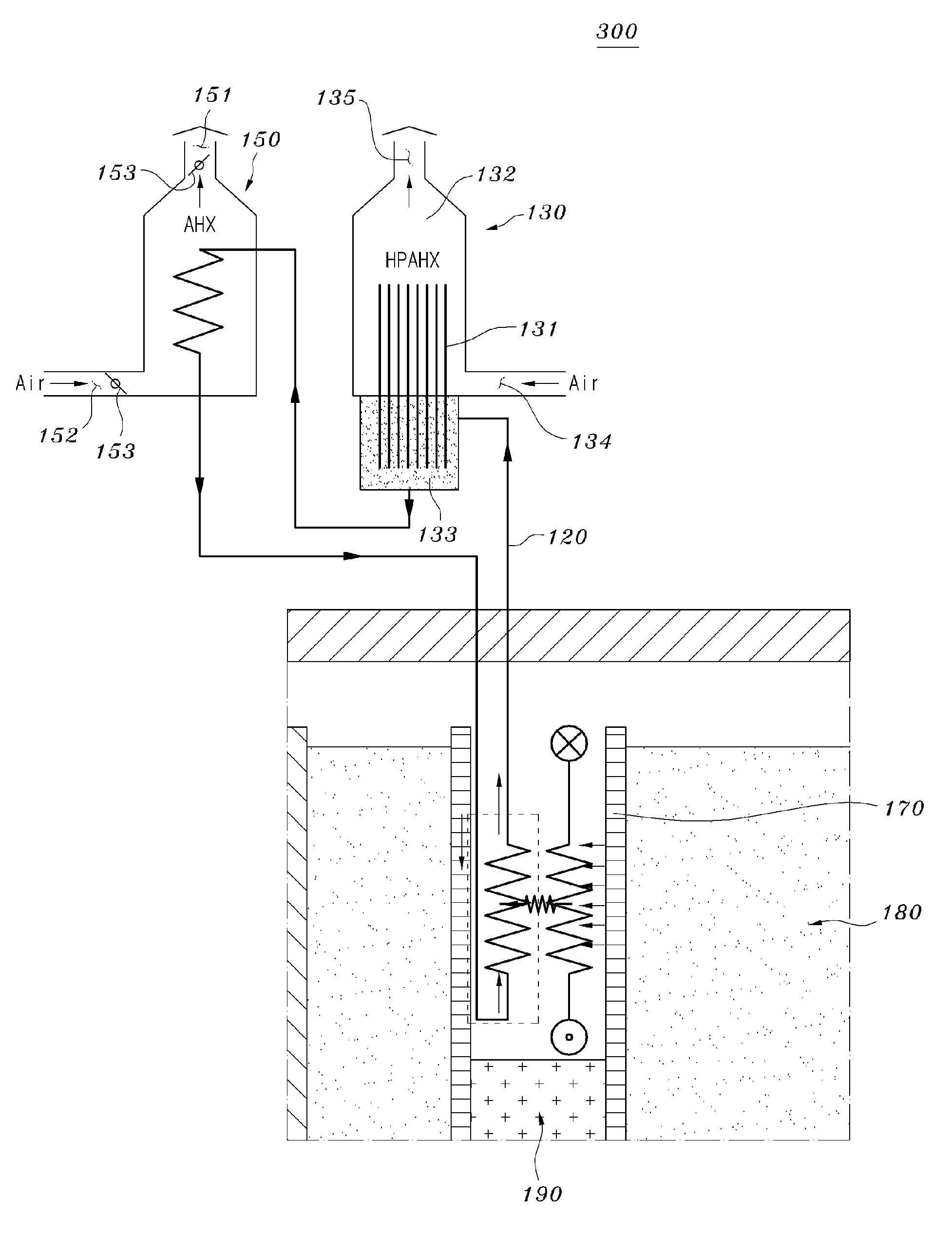
[0042]FIG. 3 is a schematic view showing a decay heat removal system including a heat pipe heat exchanger according to an embodiment of the present invention.

[0043]Referring to FIG. 3, a decay heat removal system including a heat pipe heat exchanger 100 includes a decay heat exchanger (DHX) 110, a sodium loop 120 for heat removal, a heat pipe heat exchanger (HPAHX) 130, and a sodium-air heat exchanger (AHX) 150.

[0044]The decay heat exchanger 110 serves to absorb decay heat generated by a nuclear reactor (not shown).

[0045]The heat pipe heat exchanger 130 is connected to the decay heat exchanger 110 through the sodium loop 120.

[0046]The decay heat absorbed into the decay heat exchanger 110 from the nuclear reactor is transferred to the heat pipe heat exchanger 130 through the sodium loop 120 operated by the differences in the density of sodium.

[0047]Tha...


PUM


Abstract

Disclosed herein is a decay heat removal system, including: a decay heat exchanger that absorbs decay heat generated by a nuclear reactor; a heat pipe heat exchanger that receives the decay heat from the decay heat exchanger through a sodium loop for heat removal and then discharges the decay heat to the outside; and a sodium-air heat exchanger that is connected to the heat pipe heat exchanger through the sodium loop and discharges the decay heat transferred thereto through the sodium loop to the outside. According to the decay heat removal system, a heat removal capability can be realized by the heat pipe heat exchanger at such a high temperature at which the safety of a nuclear reactor is under threat, and a cooling effect can be obtained through the sodium-air heat exchanger at a temperature lower than that temperature.

Description

CROSS-REFERENCE TO RELATED APPLICATION[0001]This application claims the benefit of Korean Patent Application No. 10-2008-0027317 filed Mar., 25, 2008 in the Korean Intellectual Property Office, the disclosure of which is incorporated herein in its entirety by reference.BACKGROUND OF THE INVENTION[0002]1. Field of the Invention[0003]The present invention relates to a decay heat removal system comprising a heat pipe heat exchanger, and, more particularly, to a decay heat removal system comprising a heat pipe heat exchanger, by which decay heat in a liquid metal-cooled reactor is passively removed.[0004]2. Description of the Related Art[0005]A liquid metal-cooled reactor is a nuclear reactor, in which energy produced by a nuclear fission reaction using fast neutrons is absorbed into a liquid metal coolant and thus transferred to a steam generator to generate steam, and then an electric generator is operated using the generated steam to produce electricity.[0006]Recently, in order to pr...

Claims


Application Information

Patent Timeline
IPC IPC(8): G21C9/00
CPCY02E30/40G21C15/18Y02E30/30G21C9/00
Inventor JEONG, HAE YONGCHO, CHUNGHOLEE, YONG BUMLEE, DONG UKEOH, JAE HYUKHA, KWI SEOK
Owner KOREA ATOMIC ENERGY RES INST
Why Eureka
Try Eureka