Structural object supporting structure, structural object mount, method for installing structural object using the mount, and solar photovoltaic system

a technology for supporting structures and structural objects, applied in the direction of machine supports, heat collector mounting/supports, light and heating apparatuses, etc., can solve problems such as troublesome screw operation, and achieve the effect of reducing the number of parts and the cost of solar photovoltaic systems, and increasing operation safety

Inactive Publication Date: 2012-12-13
SHARP KK
View PDF0 Cites 12 Cited by
  • Summary
  • Abstract
  • Description
  • Claims
  • Application Information

AI Technical Summary

Benefits of technology

[0061]According to the present invention, when the abutting portion of the structural object is abutted against the cross-piece, the position of the fitting portion of the structural object with respect to the fitting grooves of the guiding support portion is set. In this state, when an end of the structural object is slid on the cross-piece, the fitting portion of the structural object is inserted and fitted into the fitting groove of the guiding support portion to abut the stopper. Accordingly, the fitting portion of the structural object can be easily fitted into the fitting grooves of the guiding support portion. Furthermore, the movement of the structural object is restricted in a state in which the abutting portion of the structural object abuts the cross-piece, which increases the operation safety.
[0062]Further, in a structure of the invention, opposite ends of the tension bar on the underside of the solar cell panel are supported on a plurality of cross-pieces in a bridging manner, and the tension bar serves the function of reinforcing the cross-pieces. In other words, the tension bar not only serves as a component of the solar cell module made up of the solar cell panel and the tension bar, but also serves the function of a component of a mount that supports the solar cell module. This can produce a significant reduction in the number of parts and the costs of the solar photovoltaic system.

Problems solved by technology

In general, a plurality of locations of the end portions of the solar cell modules are screwed, and this screwing operation is troublesome.

Method used


Image

  • Structural object supporting structure, structural object mount, method for installing structural object using the mount, and solar photovoltaic system
  • Structural object supporting structure, structural object mount, method for installing structural object using the mount, and solar photovoltaic system
  • Structural object supporting structure, structural object mount, method for installing structural object using the mount, and solar photovoltaic system

Examples


Embodiment Construction

[0108]Hereinafter, an embodiment of the present invention will be described in detail with reference to the accompanying drawings.

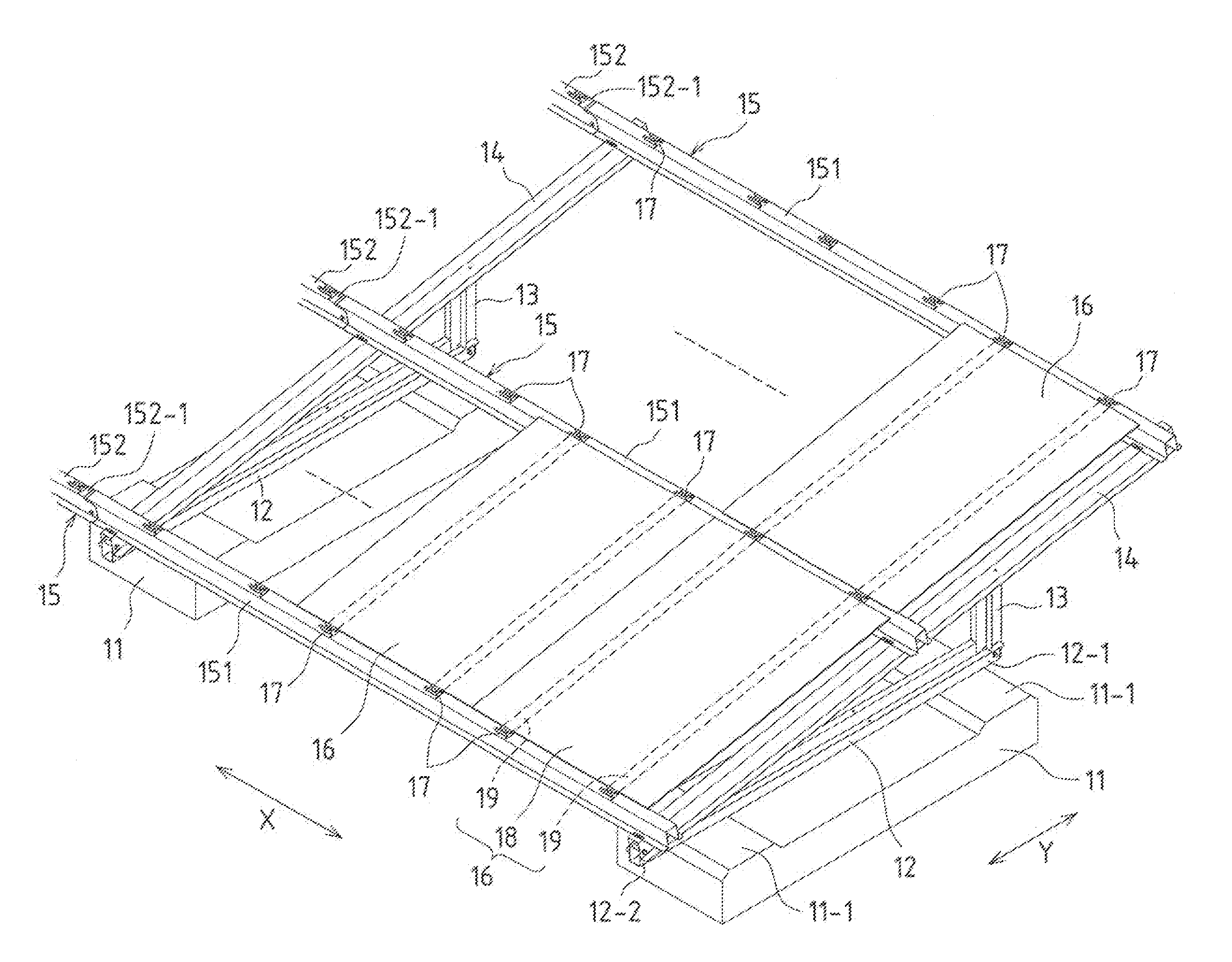
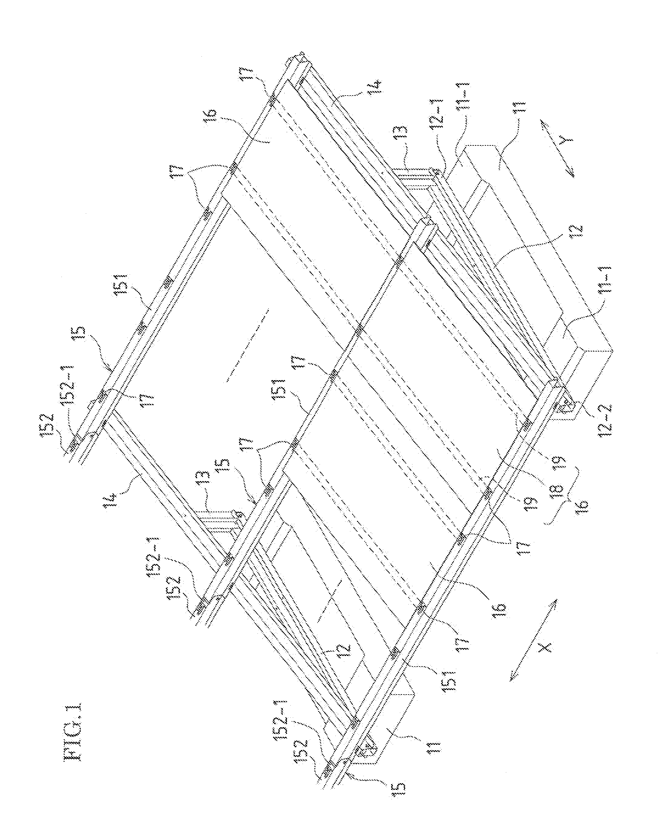
[0109]FIG. 1 is a perspective view showing a solar photovoltaic system that supports a plurality of solar cell modules using one embodiment of a structural object mount of the present invention.

[0110]This solar photovoltaic system is intended for use as a power plant, and includes many solar cell modules.

[0111]As shown in FIG. 1, the solar photovoltaic system includes a plurality of concrete foundations 11 that are laid on the ground at equal intervals. Base cross-pieces 12 are fixed to upper faces 11-1 of the respective corresponding concrete foundations 11, and are arranged side by side at equal intervals. Arms 13 are connected in an upright position to rear end portions 12-1 of the respective corresponding base cross-pieces 12. Vertical cross-pieces 14 are fixed to front end portions 12-2 of the respective corresponding base cross-pieces 12 and upper e...


PUM

PropertyMeasurementUnit
structureaaaaaaaaaa
weightaaaaaaaaaa
strengthaaaaaaaaaa

Abstract

A structural object supporting structure that supports a structural object of the present invention includes: a cross-piece on which an end of the structural object is placed; a guiding support portion disposed on the cross-piece; and a stopper provided on one end side of the guiding support portion, wherein the guiding support portion includes a fitting groove extending parallel to the cross-piece, and the end of the structural object is provided with a fitting portion that is inserted into the fitting groove of the guiding support portion from one open end of the fitting groove to abut the stopper by being slid in the longitudinal direction of the cross-piece.

Description

TECHNICAL FIELD[0001]The present invention relates to a structural object supporting structure and a structural object mount for supporting a structural object such as a solar cell module, a method for installing a structural object using the mount, and a solar photovoltaic system.BACKGROUND ART[0002]In a solar photovoltaic system, a solar cell module, which is a structural object, is fixed and supported onto a mount. One example of such a mount is a mount having a structure in which a plurality of cross-pieces are arranged parallel and fixed, and a plurality of solar cell modules are supported, spanning between the cross-pieces.[0003]In the case of this mount, end portions of the solar cell modules need to be fixed on the respective corresponding cross-pieces. In general, a plurality of locations of the end portions of the solar cell modules are screwed, and this screwing operation is troublesome.[0004]For this reason, according to the technique disclosed in Patent Document 1, fixi...

Claims


Application Information

Patent Timeline
Patent Type & Authority Applications(United States)
IPC IPC(8): F16M13/02H01L31/048B23P11/00H01L31/0203
CPCF24J2/523F24J2/5233F24J2/5239Y10T29/49826Y02E10/47Y02E10/50H02S20/00F24J2/525H02S20/23F24S25/16F24S25/13F24S25/10F24S25/617Y02B10/10
Inventor SAGAYAMA, KENICHI
Owner SHARP KK
Why Eureka
Try Eureka