Medical instrument for dissecting tissue

a technology of medical instruments and tissue, applied in the field of medical instruments for dissecting tissue, can solve the problems of unable to transmit tensile or pull forces, unable to meet the needs of patients,

Inactive Publication Date: 2007-06-12
KARL STORZ GMBH & CO KG
View PDF15 Cites 13 Cited by
  • Summary
  • Abstract
  • Description
  • Claims
  • Application Information

AI Technical Summary

Benefits of technology

[0077]This arrangement provides the advantage that the second immovable tool forms the distal point of the shaft and defines a stationary working point when that immovable tool is applied to the tissue to be dissected. In this case, thrust is exerted by the force transmission element to displace the movable tool in distal direction relative to the immovable tool, in order to cut off the tissue gripped between the immovable tool and the movable tool, and a pull force is exerted for the purpose of separating the two tools again one from the other.
[0078]According to another preferred embodiment, the at least one movable tool is protected from torsion relative to the second tool.
[0079]This feature is of advantage especially in connection with that medical instrument which has the force transmission element configured as a tube and as a helical spring in the region of the bend. The protection from torsion retains the movable tool and the second tool in fixed positions one relative to the other, with respect to torsion about the longitudinal axis of the shaft, and this even under rotary forces acting on the helical spring.
[0080]As an alternative to the configuration of the at least one movable tool as punching tool, the invention can be used, however, with like advantage if the at least one movable tool is configured as a jaw part which can be pivoted about a hinge joint and which coacts with a second tool in the manner of a pair of scissors or a forceps.

Problems solved by technology

An instrument with a bent shaft, especially if the bending radius is small, presents the problem that the force must be transmitted by the force transmission element from the movable grip element through the bend to the movable tool.
This is rendered difficult especially in view of the aim to have a slim instrument, i.e. one with a thin shaft.
However, a flexible wire can transmit only tensile or pull forces, but is not suited for transmitting thrust, or even high thrust.
Although such a force transmission element permits high thrust forces to be transferred through the bend to the movable tool, this known instrument nevertheless must be regarded as disadvantageous with that configuration of the force transmission element.
Therefore, the force transmission element may buckle or break in the region of the circumferential grooves extending over the full circumference when high thrust or sudden thrust is transferred, or may fracture when high pull forces are transferred, whereby the operating safety of the known instrument is reduced.

Method used


Image

  • Medical instrument for dissecting tissue
  • Medical instrument for dissecting tissue
  • Medical instrument for dissecting tissue

Examples


Embodiment Construction

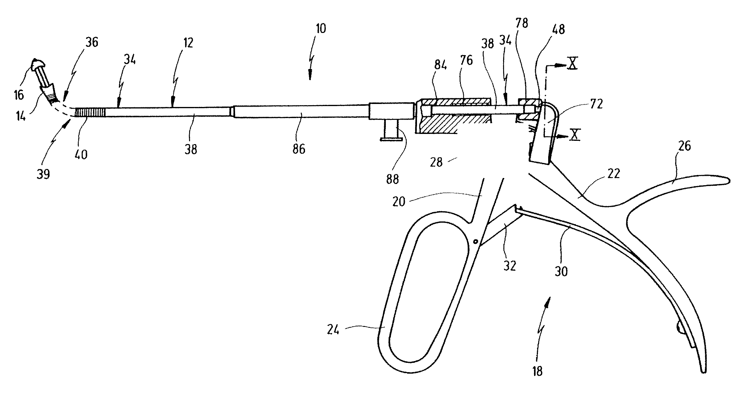
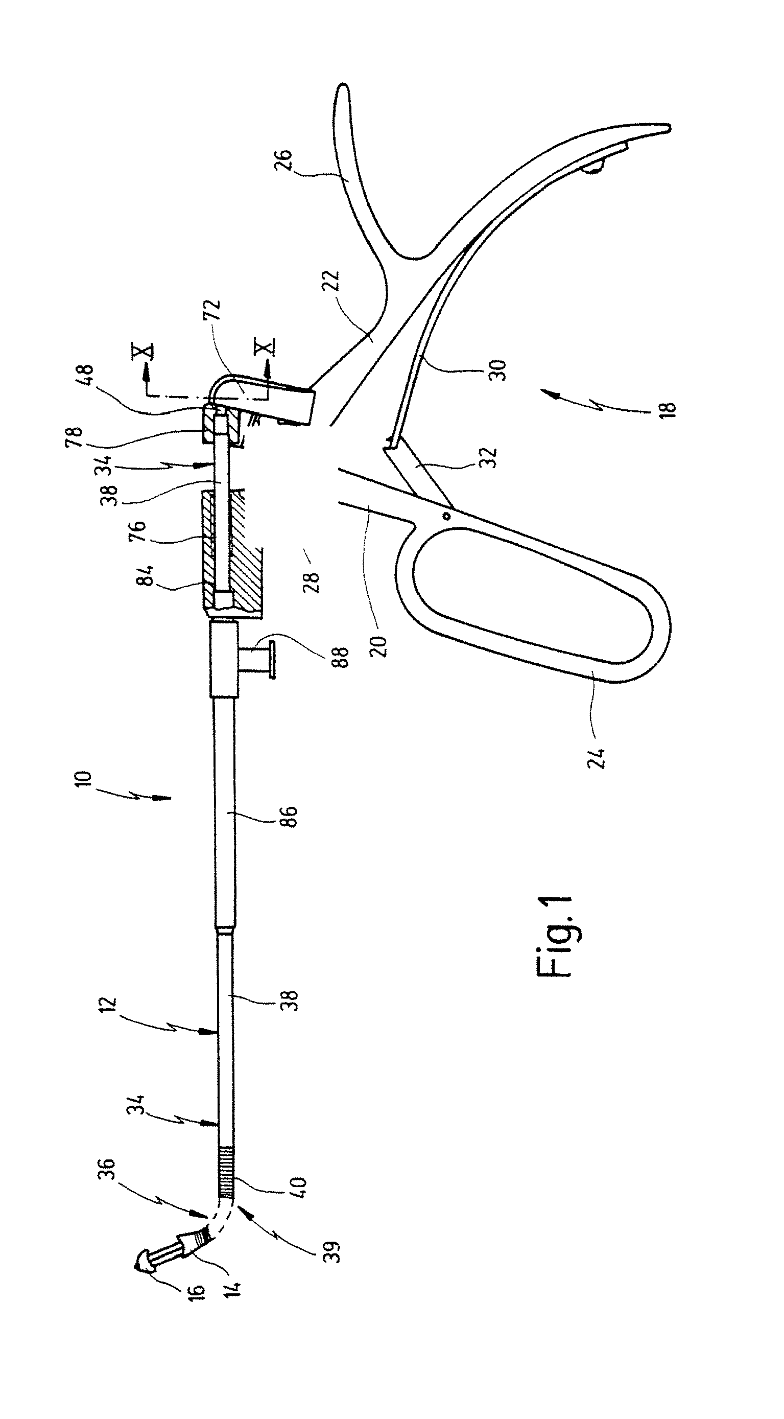
[0104]FIG. 1 shows a medical instrument according to a first aspect of the invention, indicated generally by reference numeral 10.

[0105]Instrument 10 serves for dissecting tissue in the human or animal body.

[0106]Instrument 10 comprises an elongated shaft 12. A movable tool 14 is arranged at a distal end of shaft 12. Further, an immovable tool 16 is arranged at the distal end of shaft 12, distally before movable tool 14.

[0107]At the proximal end of shaft 12, a handle 18 is arranged that comprises a movable grip element 20 and an immovable grip element 22.

[0108]Movable grip element 20 comprises a ring 24 through which one, two or three fingers can be slipped. Immovable grip element 22 comprises an extension 26, projecting in proximal direction, against which the hollow between the thumb and the index finger comes to rest during operation of the instrument.

[0109]Movable grip element 20 and immovable grip element 22 are connected one with the other via a hinge joint 28, a pivot axis of...


PUM


Abstract

A medical instrument for dissecting tissue in the human or animal body comprises a shaft. At least one movable tool is arranged at a distal end of the shaft. At least one movable grip element is arranged at a proximal end of the shaft. A force transmission element extends along the shaft, which force transmission element is movable relative to the latter and transmits thrust and/or tension forces and whose proximal end is non-positively joined to the at least one movable grip element and whose distal end is non-positively joined to the at least one movable tool. The shaft is further provided with a bend at least one point between the distal end and the proximal end. The force transmission element is configured, at least in the region of the bend, as a flexible tubular element conforming to the bend, which is guided in contact with the shaft. According to a second variant, a flattened and flexible configuration is given to the force transmission element in the region of the bend, at least locally transversely to the plane of curvature of the bend, and the force transmission element extends continuously in axial direction, transversely to the plane of curvature, at least over the inner diameter of the shaft in the region of the bend.

Description

PRIORITY APPLICATION[0001]This application is a divisional patent application of U.S. patent application Ser. No. 09 / 563,755 now U.S. Pat. No. 6,500,189, for a “Medical Instrument For Dissecting Tissue” filed May 1, 2000.BACKGROUND OF THE INVENTION[0002]The present invention relates to a medical instrument for dissecting tissue in the human or animal body.[0003]An instrument for dissecting tissue is one used for cutting and for grasping tissue, for example a punch, a pair of scissors or a forceps.[0004]Instruments of this kind are used in the context of minimally invasive surgery for dissecting tissue in the human or animal body, usually under endoscopic monitoring. To this end, instruments of that kind comprise an elongated shaft which has at least one movable tool arranged at its distal end, which usually coacts with another movable or immovable tool, arranged at the distal end of the shaft, for dissecting the tissue. For operating the at least one movable tool, such instruments a...

Claims


Application Information

Patent Timeline
Patent Type & Authority Patents(United States)
IPC IPC(8): A61B17/32A61B17/28
CPCA61B17/1611A61B17/1688A61B2017/2902A61B2017/2904
Inventor LANG, DIETERBACHER, UWEANDERS, FRIDOLIN
Owner KARL STORZ GMBH & CO KG
Why Eureka
Try Eureka