Handheld machine tool

Inactive Publication Date: 2013-06-27
ROBERT BOSCH GMBH
View PDF4 Cites 13 Cited by
  • Summary
  • Abstract
  • Description
  • Claims
  • Application Information

AI Technical Summary

Benefits of technology

[0005]The present invention is based on the objective of increasing the operating

Problems solved by technology

A drive-torque limitation device is assigned to the supplementary handle, which limits the drive torque output by the drive motor when the supplementary handle is not mounted on the housing.
The limitation of the drive or motor torque is made to a torque level that lies below the maximum torque able to be delivered by the drive motor.
On the other hand, if the supplementary handle is not mounted on the housing, or if it is mounted incorrectly, the drive motor i

Method used


Image

  • Handheld machine tool
  • Handheld machine tool

Examples


Embodiment Construction

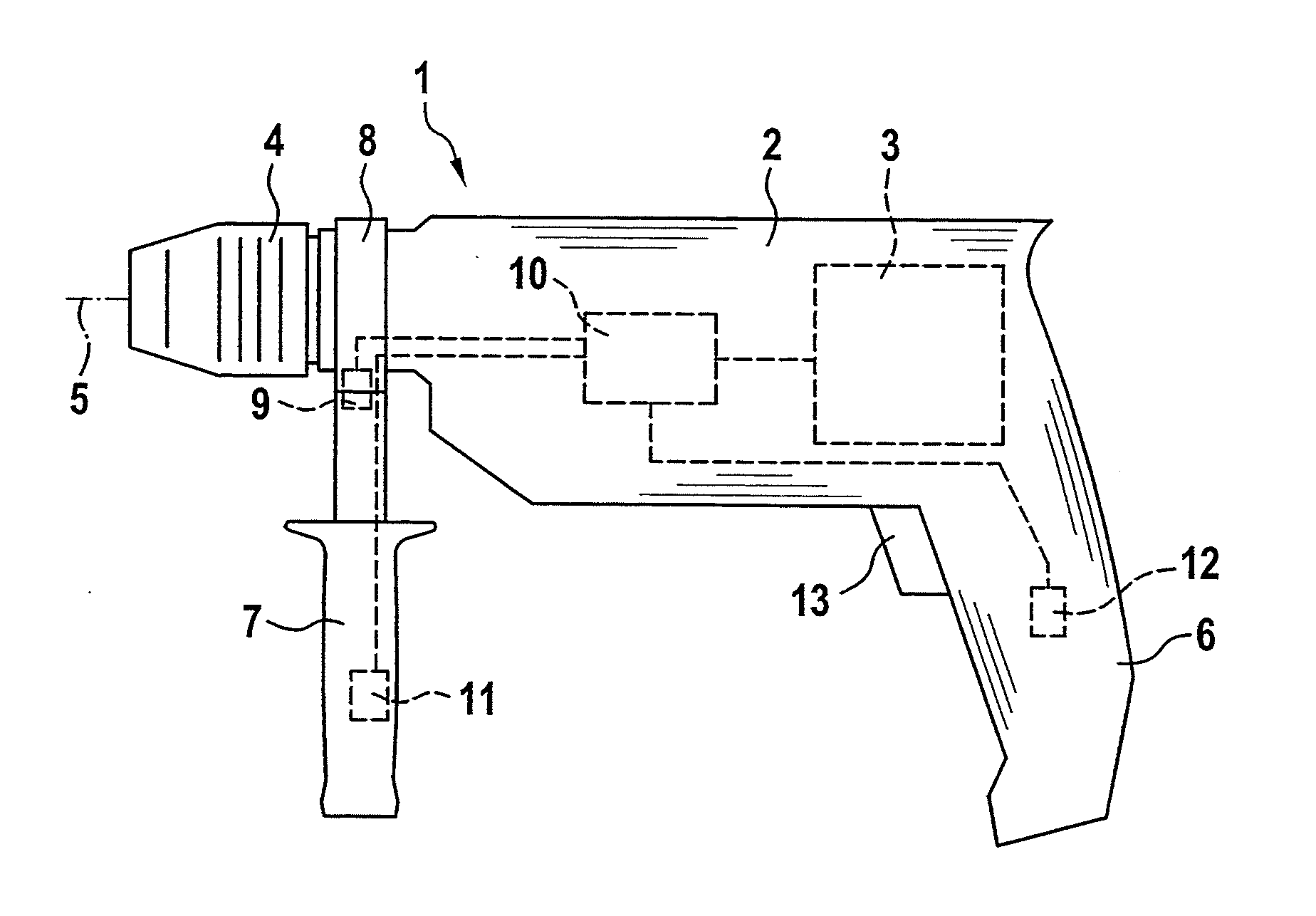
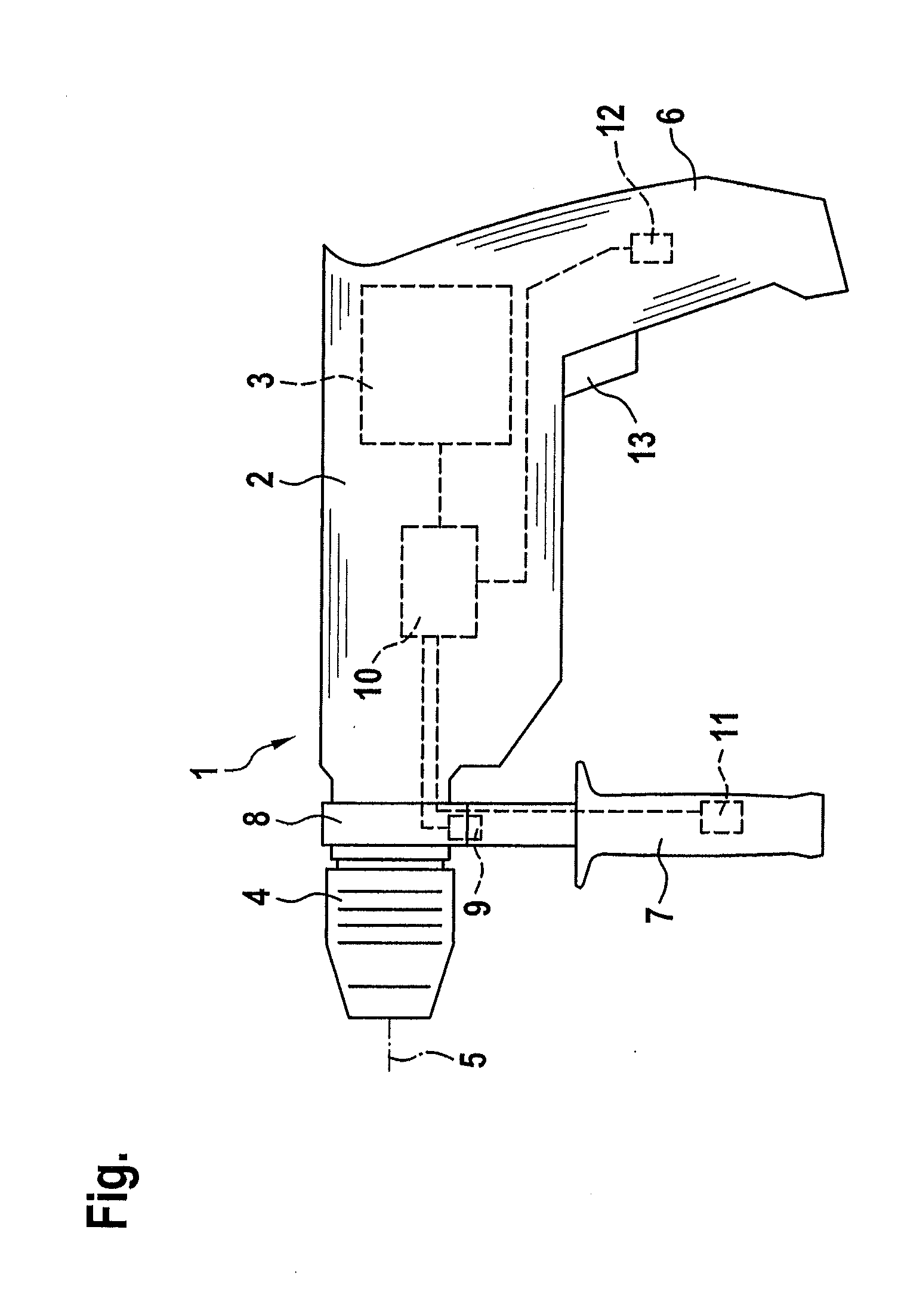
[0016]Handheld machine tool 1 shown in FIG. 1 is a power drill which has an electric drive motor 3 in a housing 2, via which a sketched tool 5, which is accommodated in a tool receiving device 4 implemented as drill chuck, is able to be driven. Housing 2 of handheld machine tool 1 has a main handle 6, which is developed in one piece with the housing. In addition, a supplementary handle 7 is provided, which is optionally linkable to housing 2 on a connection segment 8, which may be part of housing 2. In the linked state, supplementary handle 7 is fixedly joined to housing 2 via connection segment 8. If needed, however, supplementary handle 7 can be detached from housing 2 again. Connection segment 8 for accommodating supplementary handle 7 is situated in the front region of housing 2, adjacent to tool receiving device 4. Main handle 6 is located in the rear region of the housing lying opposite.

[0017]The connection between connection segment 8 on housing 2 and supplementary handle 7 i...


PUM

PropertyMeasurementUnit
Timeaaaaaaaaaa
Torqueaaaaaaaaaa

Abstract

A handheld machine tool has a drive motor and a supplementary handle which is mounted on the housing of the handheld machine tool and is assigned a drive-torque limitation device, the drive-torque limitation device limiting the drive torque to a torque level below a maximum torque if the supplementary handle is not mounted on the housing.

Description

BACKGROUND OF THE INVENTION[0001]1. Field of the Invention[0002]The present invention relates to a handheld machine tool having a drive motor and a supplementary handle which is mountable on the housing of the handheld machine tool.[0003]2. Description of the Related Art[0004]From published German patent application document DE 10 2009 047 394 A1, a handheld machine tool is known, which is equipped with a supplementary handle, to be mounted on the housing if needed. Situated on the supplementary handle are two electrically conductive contact elements, which are set apart from each other and part of a current circuit, whose capacity changes when the user grips the supplementary handle. The capacity change is detected by a detection device and wirelessly transmitted to an evaluation unit in the handheld machine tool. If the evaluation unit detects that the user is gripping the supplementary handle incorrectly, the maximum drive output of the electrical drive motor in the handheld mach...

Claims


Application Information

Patent Timeline
IPC IPC(8): H02P31/00
CPCB23B45/001B23B2260/122B25F5/026H02P31/00B23B2260/128
Inventor KOEDER, THILO
Owner ROBERT BOSCH GMBH
Why Eureka
Try Eureka