Holster

a technology for holsters and handguns, applied in the field of holsters, can solve the problems of increasing manufacturing costs, complicated mechanisms, and inability to accommodate accessories mounted forward of the trigger guard of handguns, and achieve the effect of less retention level and not readily visibl

Active Publication Date: 2014-02-20
VISTA OUTDOOR OPERATIONS
View PDF9 Cites 47 Cited by
  • Summary
  • Abstract
  • Description
  • Claims
  • Application Information

AI Technical Summary

Benefits of technology

[0007]Embodiments of the invention include the individual mechanisms as well. A feature and advantage of embodiments is a latch hood operated by a push button attached to an axially movable member that slide or moves out of a latching engagement with the latch hood and the latch hood by way of a spring bias rotates to the open position allowing removal of the handgun.
[0008]The retention sleeve may include at least one projecting that extends out on one end of the retention sleeve. In one embodiment, the projecting component extends towards the front of the gun, downwardly in the holster body, and is sized to capture a spring. The spring engages a spring catch of the interior of the holster body to provide a bias of the sleeve towards the open top of the holster. A feature and advantage of the holster is that the pivoting latch hood can remain open when the handgun is reholstered to provide a lesser retention level than with the latch hood in a capture position.
[0009]A feature and advantage of embodiments is the release lever coupled to the retention sleeve. When the release sleeve and latch hood are engaging with each other, pressing downward (or forward) on the release lever simultaneously or sequentially actuates and disengages the catch wedge of the latch member from the ejection port of a handgun and disengages the prongs from the latch hood from the compartments, pockets, or sleeves of the retention sleeve. A spring or other resilient material may be placed underneath ejection port capture member for primary or supplemental bias in the obstruction position with the ejection port.
[0010]A feature and advantage of embodiments of the invention is that the retention of the firearm at the slide allows the holster to be configured to receive firearms with laser illumination sights units mounted forwardly of the trigger guard. Conventional holsters with trigger guard retention mechanisms cannot receive firearms with such laser sights.
[0011]A feature and advantage of embodiments of the invention is a single thumb actuated push button that releases the spring loaded pivoting latch hood h and a gun withdrawal obstruction member. In embodiments the obstruction member may be on the trigger guard, in embodiments on the ejection port.
[0012]A feature and advantage of embodiments of the invention is that a single motion with the thumb depression can actuate the latch hood to snap open providing a provocative signal to a potential suspect that the gun may be deployed. A feature and advantage of the embodiments of the invention is that the actuation button is not readily visible. Moreover, in embodiments, the push button is positioned in a difficult to access position by others not wearing the holster. In embodiments the button is forward of the hood and intermediate the firearm and holster attachment portion, for example, a belt clip. Also, the user may mute the latch hood “snap” by preventing it from snapping open with the same hand actuating the push button.

Problems solved by technology

Current rigid polymer holsters that utilize retention mechanisms for preventing removal of the handgun typically secure the handgun at the trigger guard Holsters that utilize trigger guard latch mechanisms generally cannot accommodate accessories mounted forwardly of the trigger guard of the handgun, such as laser sights.
Such requires different mold sets for each configuration greatly increasing manufacturing cost.
Additionally when a holster has more than one retention feature, often mechanisms are either complicated, not reliable, and / or the actuation buttons are readily visible.
Moreover, in embodiments, the push button is positioned in a difficult to access position by others not wearing the holster.

Method used


Image

  • Holster
  • Holster
  • Holster

Examples


Embodiment Construction

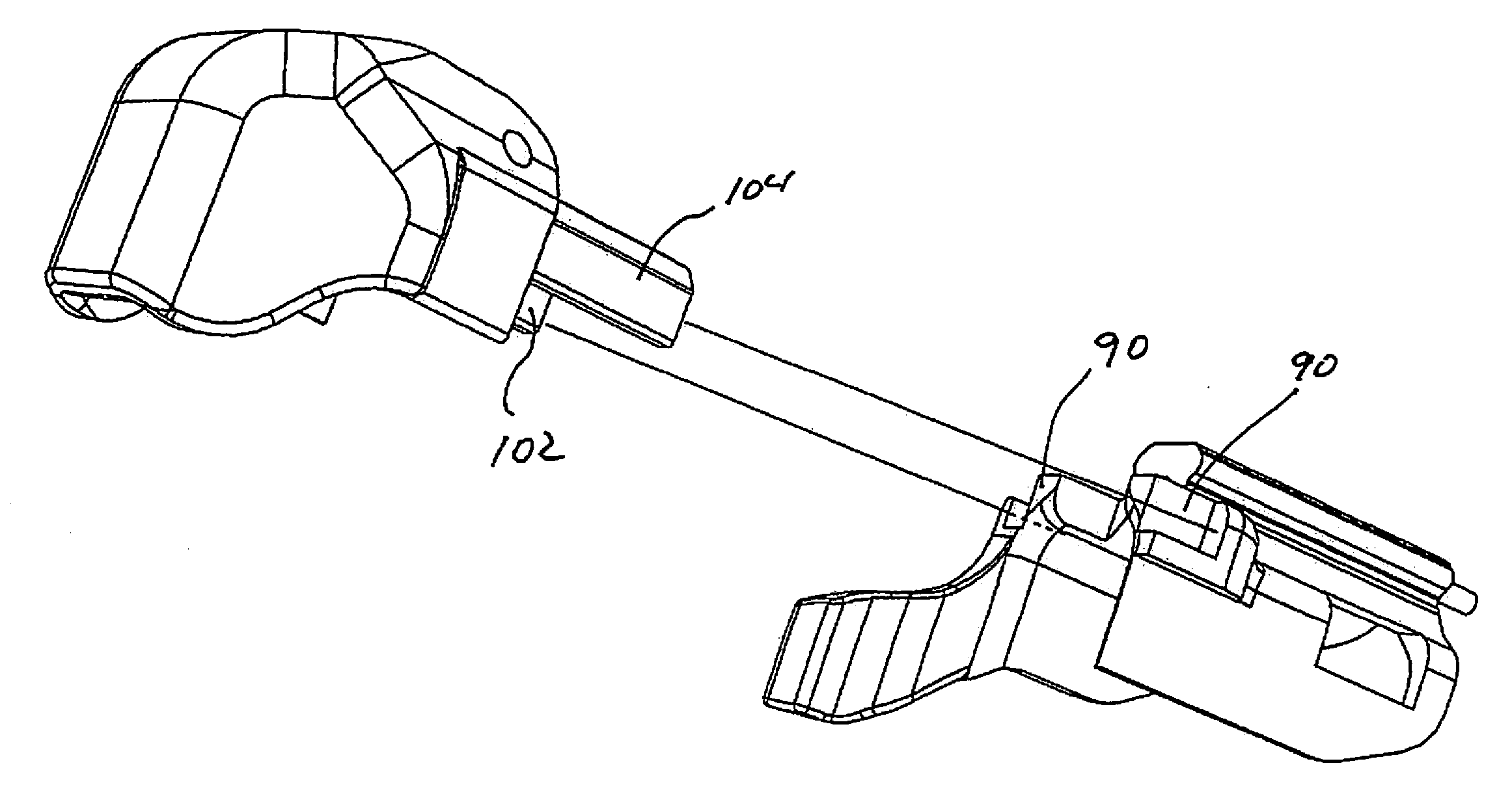
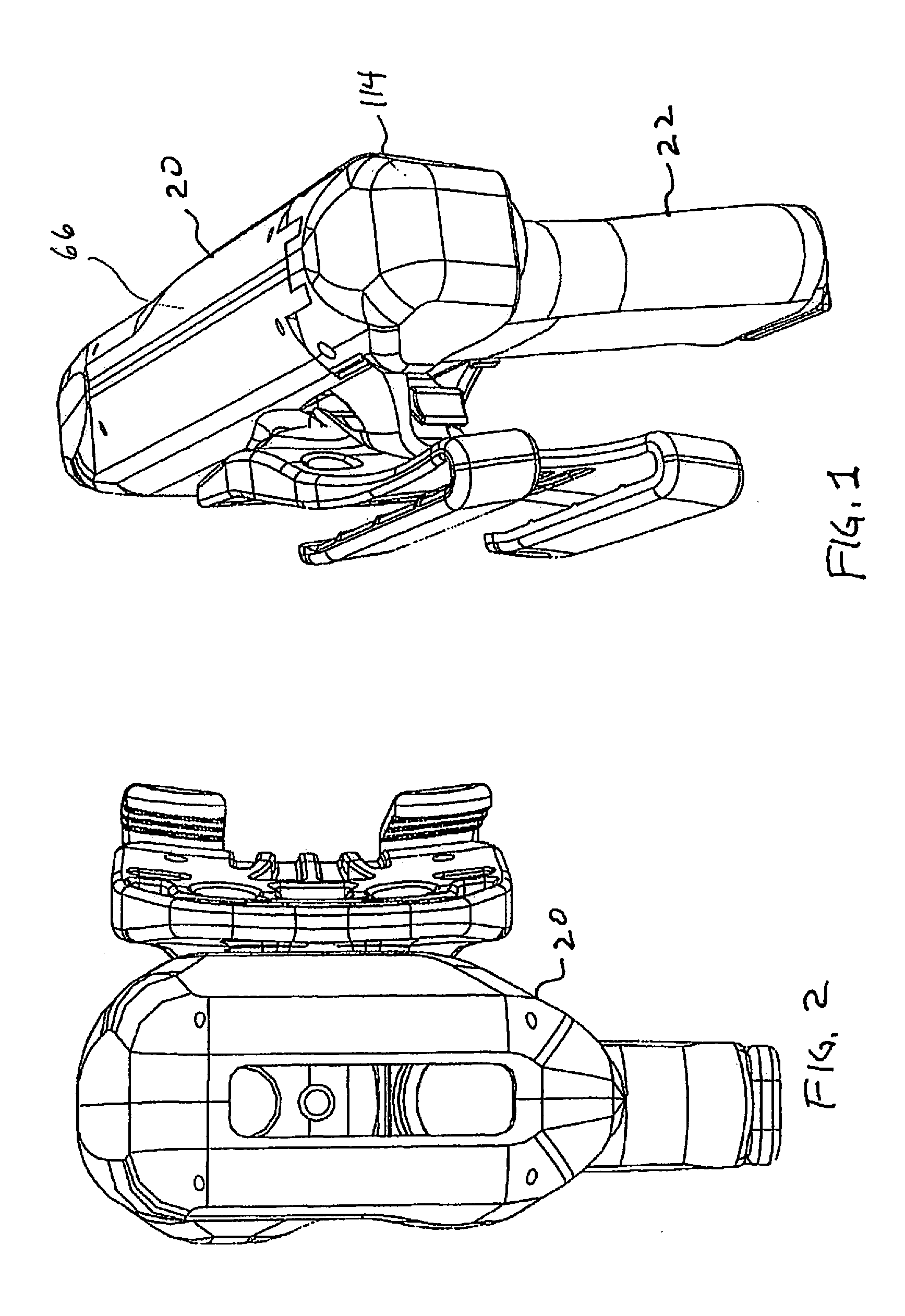
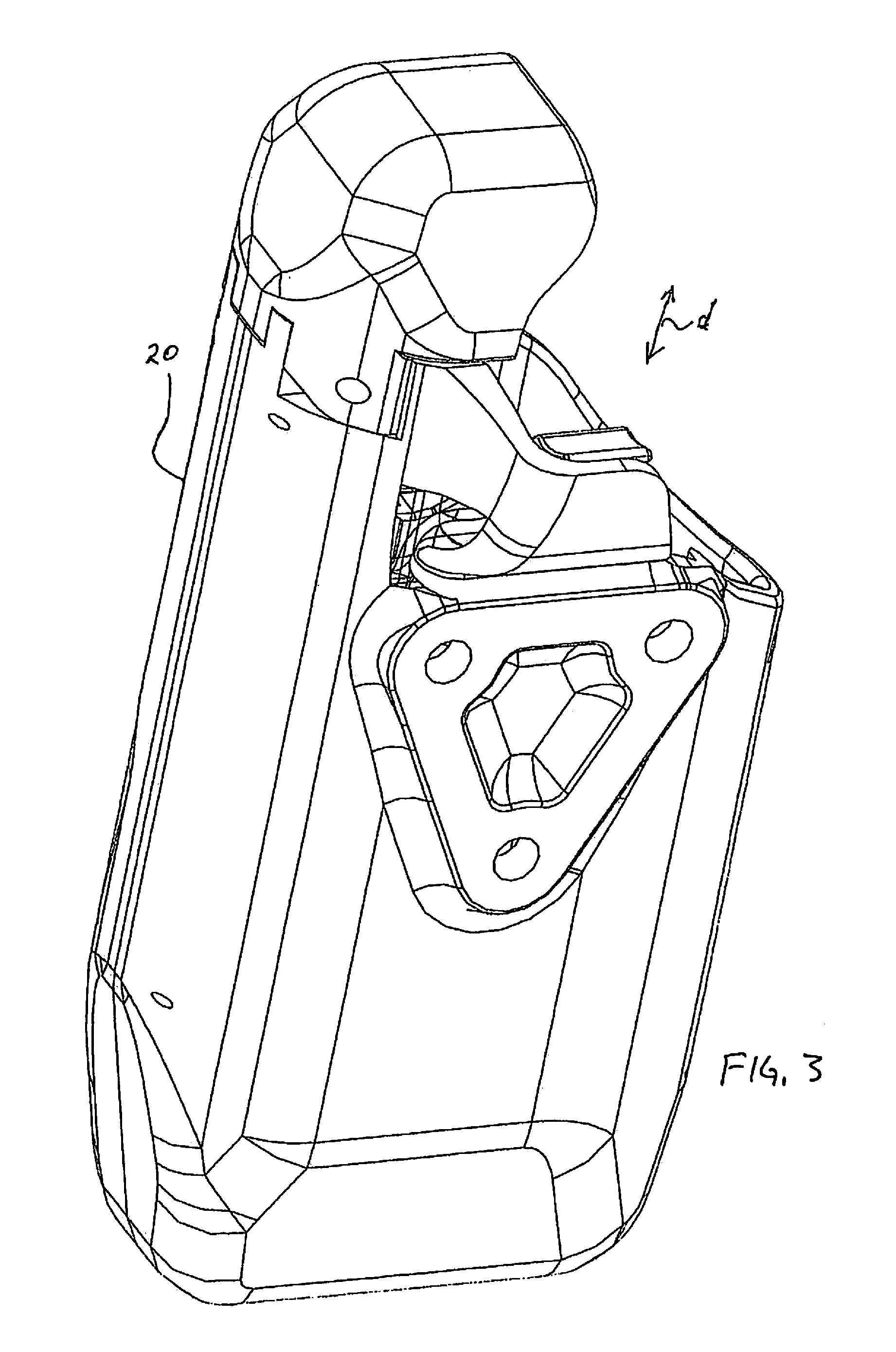
[0044]Referring to FIGS. 1-7, a holster 20 is configured to receive a handgun 22 and in particular embodiments is equipped with two retention means commonly actuated. The holster comprises generally a holster body 30, linkage configured as a slidably engaged internal retention sleeve 34 connected to the body, a handgun withdrawal obstructing member 40 configured as an ejection port obstruction member connected to the body, and a latch hood 46 connected to the body. A holster holding device such as an attachment clip 50 may be used to secure the holster to a belt or other harness. The handgun is a conventional semi-automatic with a slide 51 and ejection port 52 with a surface 55 that extends transverse to the direction d of insertion and removal of the firearm. The holster has a longitudinal axis a extending parallel to the insertion / withdrawal direction. Of note, the holster provides functionality even when the handgun has accessories such as laser illumination sights 53.

[0045]The h...


PUM

PropertyMeasurementUnit
forward forceaaaaaaaaaa
U-shapeaaaaaaaaaa
sizesaaaaaaaaaa

Abstract

A holster for a handgun that comprises a holster body with a handgun cavity for receiving and retaining the handgun by way of a obstructing member at the ejection port and at the rear portion of the handgun slide. Moreover, a single obscured push button actuates both mechanisms. An internal retention sleeve having an inverted U-shape is slidingly mounted within the holster body and movable between a first securement position and a second release position. The sleeve having an integral thumb button depressible downwardly whereby the sleeve moves downwardly within the body to release a ejection port stop catch and the latch hood. The sleeve biased toward a normal retention position, the handgun withdrawal obstructing member biased toward the normal retention position, the latch hood biased toward a release position but having a normal latched obstructing position until released by the sleeve.

Description

BACKGROUND OF THE INVENTION[0001]Current rigid polymer holsters that utilize retention mechanisms for preventing removal of the handgun typically secure the handgun at the trigger guard Holsters that utilize trigger guard latch mechanisms generally cannot accommodate accessories mounted forwardly of the trigger guard of the handgun, such as laser sights. Moreover, a particular holster design for different handguns, or for the same handgun with accessories, will typically require entirely new component configurations for a particular model of holster. This is due to the requirement for proper operation of the release mechanism of a very close form fit between the handgun and the holster. Such requires different mold sets for each configuration greatly increasing manufacturing cost. Additionally when a holster has more than one retention feature, often mechanisms are either complicated, not reliable, and / or the actuation buttons are readily visible. It would be advantageous to have le...

Claims


Application Information

Patent Timeline
Patent Type & Authority Applications(United States)
IPC IPC(8): F41C33/02
CPCF41C33/0272F41C33/0227F41C33/0263Y10S224/912Y10T29/49863
Inventor YEATES, ERIC M.
Owner VISTA OUTDOOR OPERATIONS
Why Eureka
Try Eureka