Tool for Deflecting Spray from Flange Coupling

a technology for flange couplings and tools, which is applied in the direction of flanged joints, pipe joints, pipe elements, etc., can solve the problems of unsatisfactory, unfavorable work, and injuring workers, and achieve the effect of increasing or decreasing the tension of the strap

Inactive Publication Date: 2014-04-10
GEARENCH DIV OF ORBIX
View PDF10 Cites 12 Cited by
  • Summary
  • Abstract
  • Description
  • Claims
  • Application Information

AI Technical Summary

Benefits of technology

[0006]Disclosed herein is a spray deflector for blocking discharge from a flanged pipe coupling having a pair of flanges positioned adjacent one another and separated by a gap. The spray deflector has a strap with first and second ends that is configured to circumferentially surround the flanges and cover the gap. The spray deflector also has a tensioning mechanism for increasing or decreasing the tension in the strap around the flanges.

Problems solved by technology

Such spray may be hazardous to workers, and also to the environment.
If such fluid sprays onto a worker, it may injure the worker.
In addition, if such oil or chemical sprays to a shop environment, it may cause undesirable conditions, such as slip and fall hazards in the vicinity of the spray.
Furthermore, if such oil or chemical sprays into the natural environment, it may pollute, or otherwise contaminate the environment.
For example, in situations where a second worker is nearby, the shield would not necessarily protect the second worker.
In addition, because the shield still allows the spray to exit the coupling, albeit in a direction away from the worker, the spray may still harm the environment,

Method used


Image

  • Tool for Deflecting Spray from Flange Coupling
  • Tool for Deflecting Spray from Flange Coupling
  • Tool for Deflecting Spray from Flange Coupling

Examples


Embodiment Construction

[0014]The foregoing aspects, features, and advantages of the present technology will be further appreciated when considered with reference to the following description of preferred embodiments and accompanying drawings, wherein like reference numerals represent like elements, In describing the preferred embodiments of the technology illustrated in the appended drawings, specific terminology will be used for the sake of clarity. However, the technology is not intended to be limited to the specific terms used, and it is to be understood that each specific term includes equivalents that operate in a similar manner to accomplish a similar purpose.

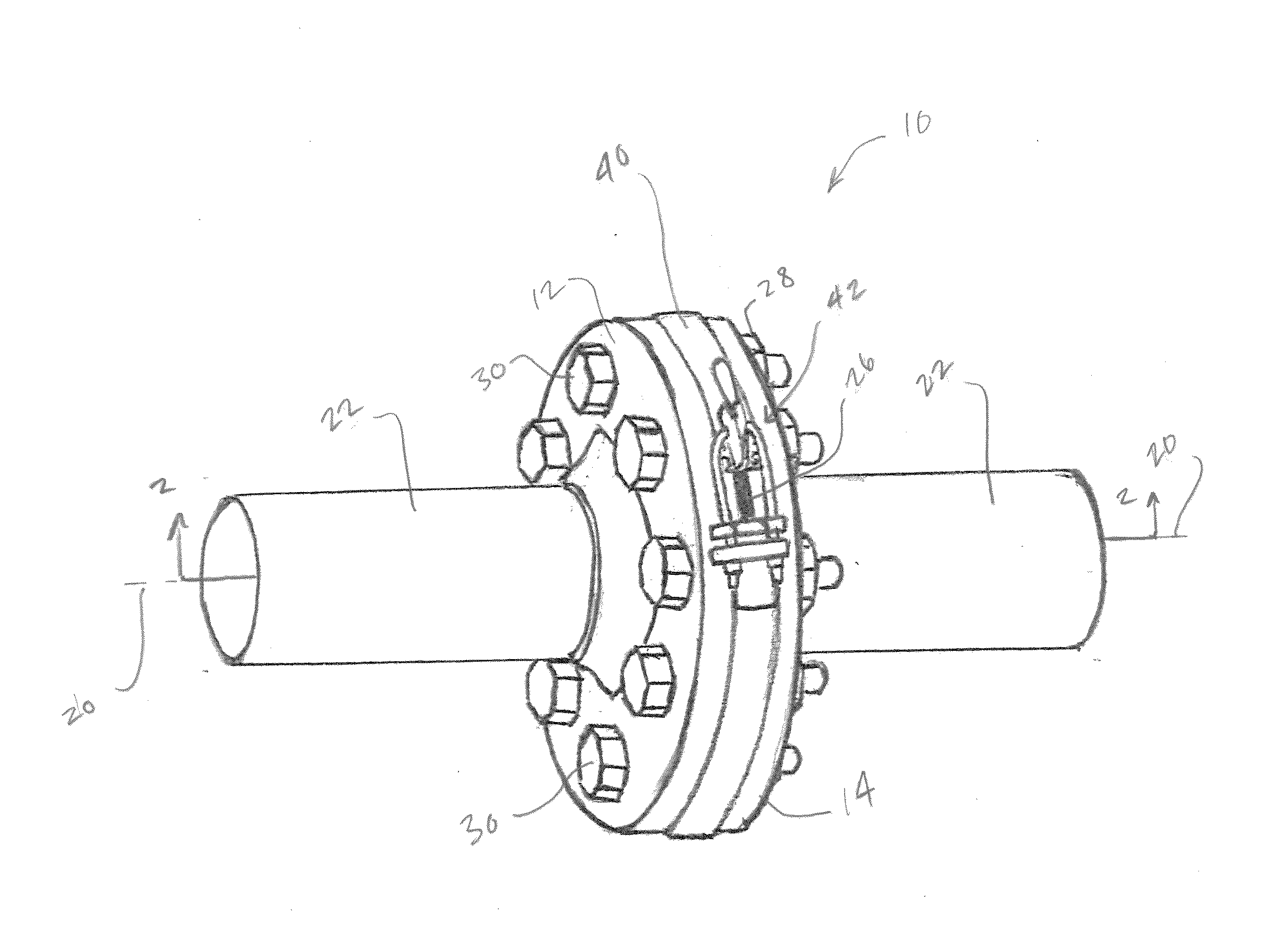
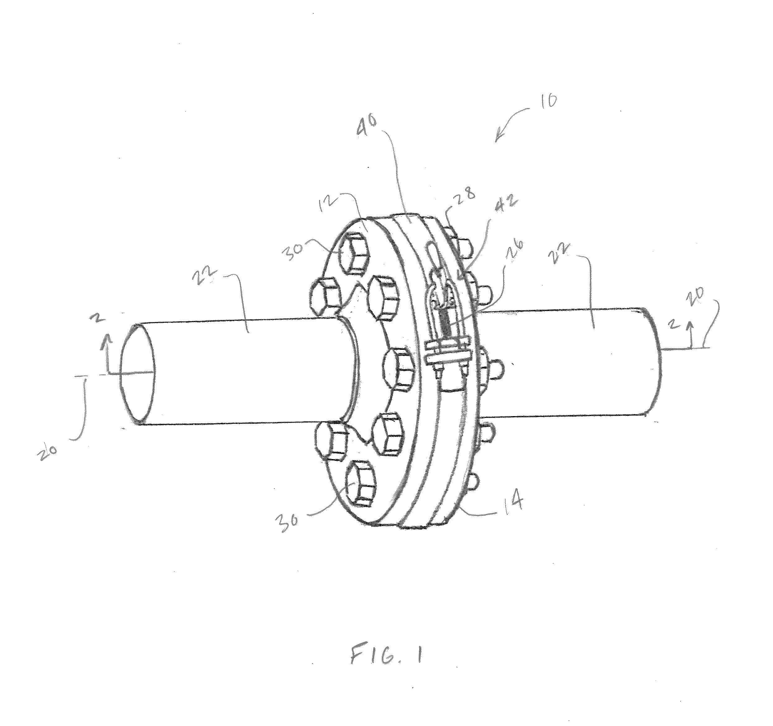
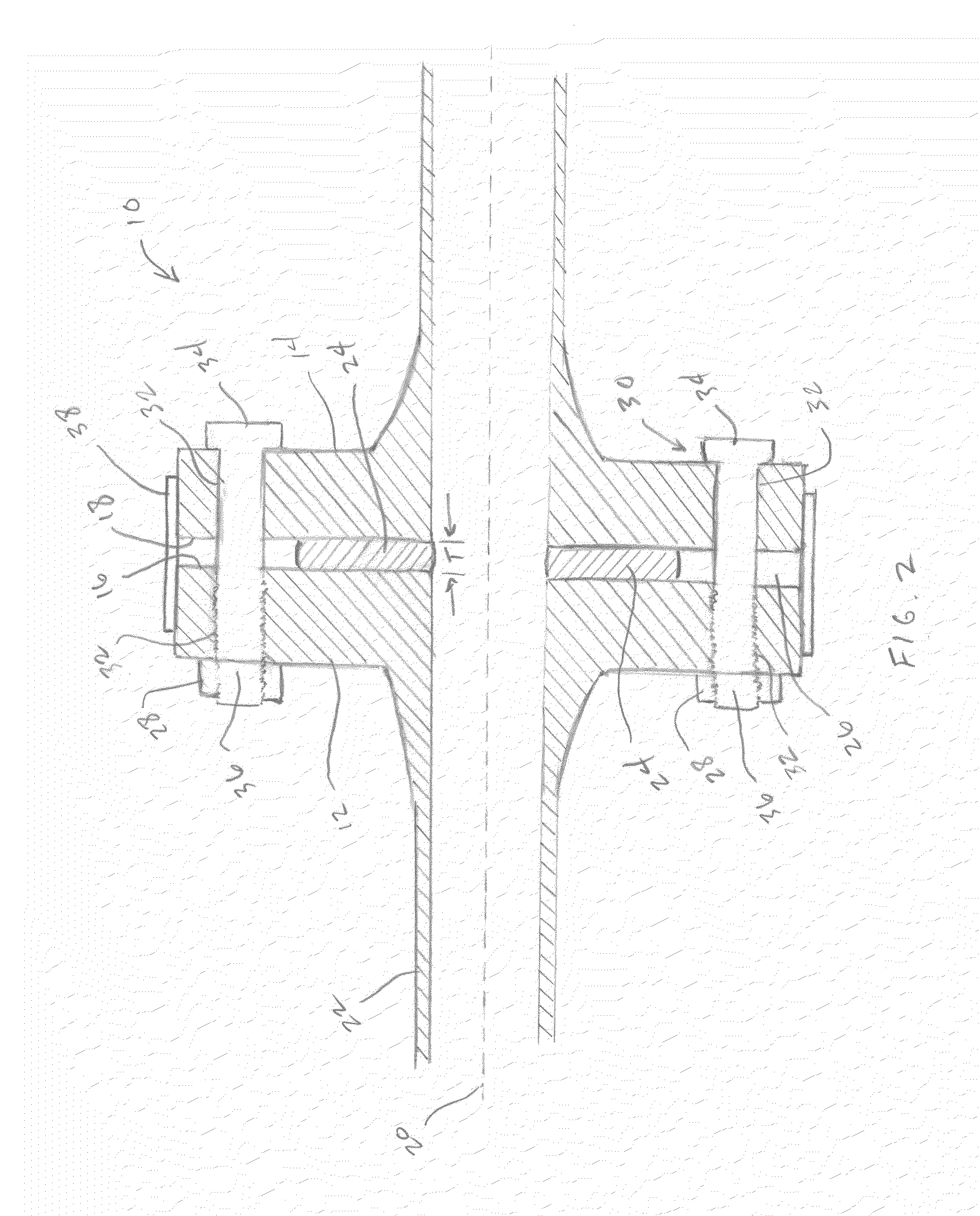
[0015]FIG. 1 is a perspective view of a flanged pipe coupling 10 according to an embodiment of the present technology, and FIG. 2 is a cross sectional side view of the flanged pipe coupling 10 taken along line 2-2 of FIG. 1 As best shown in FIG. 2, the flanged pipe coupling 10 includes flanges 12, 14 having flange faces 16, 18. Flange faces 16,...


PUM


Abstract

An apparatus for blocking discharge from a flanged pipe coupling, including a s trap configured to surround, and cover a gap between flanges. The apparatus includes a tensioning mechanism with a lever pivotally coupled to the strap, a clamp pin mounted on the opposing end of the strap, and an adjustment pin on a side of the clamp pin opposite the lever. Holes extend through ends of the clamp and adjustment pins. The tensioning mechanism includes a bolt having ends, and a mid-portion looped around the lever, so that portions of the bolt on opposing ends of the mid-portion are generally parallel and project through the holes. A fastener is mounted onto each bolt end on a side of the adjustment pin opposite the clamp pin. When the lever pivots away from the clamp pin, contact between the lever and bolt urges the ends of the strap together, increasing tension therein,

Description

BACKGROUND OF THE INVENTION[0001]1. Field of the Invention[0002]This technology relates to pipe couplings. In particular, this technology relates to tools for deflecting spray from between flanges of flanged pipe couplings.[0003]2. Brief Description of Related Art[0004]Occasionally, when disconnecting the bolts from the flanges of a pipe coupling, some liquid may spray out of the coupling, even though the flow line may have been relieved of pressure. Such spray may be hazardous to workers, and also to the environment. For example, the fluid that sprays out of the coupling ay be oil, or a dangerous chemical. If such fluid sprays onto a worker, it may injure the worker. In addition, if such oil or chemical sprays to a shop environment, it may cause undesirable conditions, such as slip and fall hazards in the vicinity of the spray. Furthermore, if such oil or chemical sprays into the natural environment, it may pollute, or otherwise contaminate the environment.[0005]Shields for use in ...

Claims


Application Information

Patent Timeline
Patent Type & Authority Applications(United States)
IPC IPC(8): F16L55/17
CPCF16L23/003F16L23/167F16L55/17
Inventor WEBB, ANDREWWEBB, PETE
Owner GEARENCH DIV OF ORBIX
Why Eureka
Try Eureka