Knitted glove with controlled stitch stretch capability

a technology of knitted gloves and stretchability, which is applied in the field of knitted gloves, can solve the problems of not revealing knitted gloves or liners, the shape cannot accommodate individual fingers and hands in size and shape, and the denier of yarns is extremely difficult to change, etc., and achieves less stretch, tight feel, and enhanced or reduced stretch capability

Active Publication Date: 2007-05-08
ANSELL HEALTHCARE PRODS
View PDF18 Cites 44 Cited by
  • Summary
  • Abstract
  • Description
  • Claims
  • Application Information

AI Technical Summary

Benefits of technology

[0011]The present invention is directed towards knitted gloves and liners and a method of making these knitted gloves and liners using a continuous single yarn and array of knitting needles matching the yarn denier. The invention relates to the fit of knitted gloves or liners on a human hand. Specifically, the stitch dimension and the number of courses used to knit each of the standard eight major glove components and their sections of the glove are altered to provide a glove geometry, which is anatomically matched to a human hand, providing increased stretch capability in areas that flex during movement. This increased stretch capability provides the wearer with a tight-fitting glove, which still provides a comfortable glove feel and an easy movement capability. These geometric alterations help conform the glove or liner to fit better human hands. The alterations permit manufacturing of gloves or liners with nearly perfect fit to the hand because of their tapered fingertips, expanded knuckles, tapered palm areas and expanded cuff width.
[0013]In a second embodiment of the stitch dimension, the tension in the yarn that is being knitted is increased or decreased under computer control. The yarn from a spool is clamped between a pair of pinch rollers, one of which may optionally be a computer-controlled feeding roller. Due to the pinching action, the tension in the yarn in the knitting head is not transmitted to the yarn spool. The computer controls the tension in the yarn in the segment between the pinch roller and the knitting head by means of a computer-controlled tension adjustment mechanism. This adjustment mechanism may comprise a spiral spring carrying an arm through which the yarn passes. A spiral spring is attached to the arm, and the other end of the spiral spring is attached to a stepper motor. The computer rotates the stepper motor shaft, thereby increasing or decreasing the tension in the yarn in the segment between the pinch roller and the knitting head. The tension in the knit stitch limits its stretch capability. A full course stitched with increased tension has reduced stretch capability of that course. Accordingly, a fabric knitted with a number of courses with increased tension exhibits reduced stretch capability.
[0014]In a third embodiment of stitch dimension, a stitch can be missed in knitting a course. This decreases the overall stretch capability of the course. On the other hand, an additional stitch can be picked from the stitch to increase the overall length of a course to provide increased stretch capability.
[0016]The course knitted with a different stitch dimension essentially provides more yarn or less yarn at a given glove location, thereby providing enhanced or reduced stretch capability. The sections, which are required to have less stretch and, therefore, have a tight feel, are made with stitches that incorporate a smaller length of yarn and / or a high tension or have one or more stitches less than the adjacent courses. Conversely, when a section requires increased stretch capability, the stitches are made with increased yarn length and / or with reduced tension or may have one or more stitches picked up in the courses compared to adjacent courses.

Problems solved by technology

Changing needles or the denier of a yarn is extremely difficult in a continuous process and generally a continuous yarn of pre-selected denier and a corresponding needle size are commercially used.
While this standardization in needle size and number of courses permits the manufacturing of a glove or liner with a standard shape, that shape does not accommodate variations in size and shape of individual fingers and hands.
This device minimizes the fluctuations in knitting yarn tension due to sudden demand and is not programmed to alter the knitting yarn tension to adjust stitch dimensions.
This patent discloses the hardware necessary for stitch dimension control and does not disclose a knitted glove or liner with anatomic features providing improved fit.
First, the fit across finger knuckles and the center of the palm is tight, reducing glove or liner flexibility and ultimately reducing hand dexterity.
Second, the standard gloves or liners bag or gap in areas where the hand normally tapers, e.g., like the lower palm and wrist area.
This bagginess or gapping results in excess fabric, which can bunch and catch on protruding objects.
Additionally, excess fabric at the lower palm created by the standard glove or liner shape causes an irregular foam line on those liners that are dipped in latex.
Finally, the excess fabric at the lower palm of the standard glove or liner causes a high scrap rate in printing information on the gloves or liners.
These processes as used on the larger gloves, however, may produce gloves that have improved fit across the knuckles, but do not address the excess fabric in areas where the hand normally tapers, like the lower palm and wrist, since the shrinkage is uniform across the glove.
Additionally, tumbling or a laundry process would require an additional manufacturing step as well as additional labor, both of which would increase the cost of the finished product.
A standard tumbling process, using constant heat and time, would also fail to create the desired gloves and liners because of differences in heat sensitivity of the fibers selected to knit the various gloves and liners in a manufacturing operation.
Further, these types of post-knitting processes would require additional development and manufacturing time to determine appropriate time and heat combinations to optimize the production of a particular glove or liner.

Method used


Image

  • Knitted glove with controlled stitch stretch capability
  • Knitted glove with controlled stitch stretch capability
  • Knitted glove with controlled stitch stretch capability

Examples


Embodiment Construction

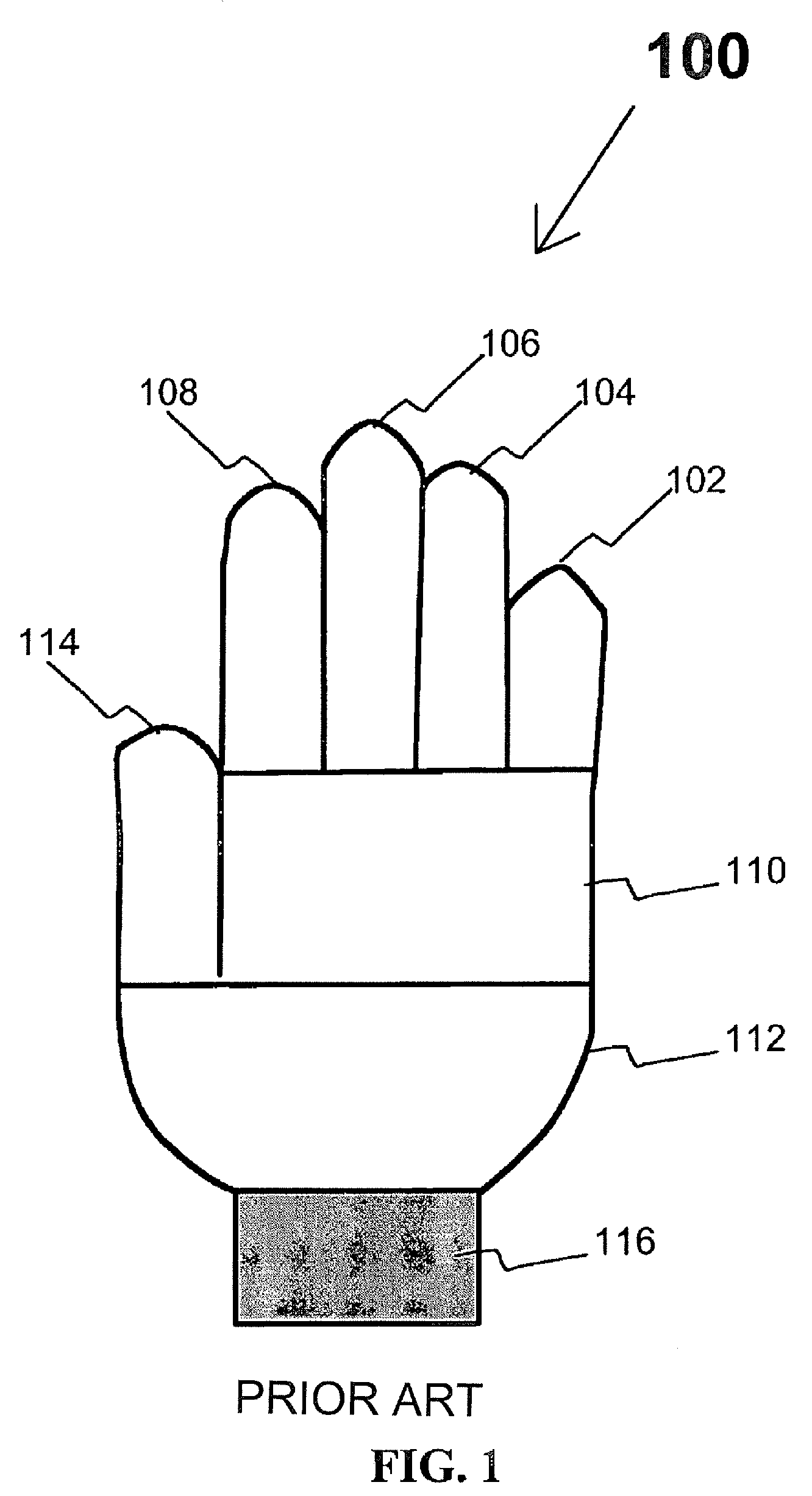
[0022]The prior art, as shown in FIG. 1, is a glove 100, having eight major glove components. These components include a pinky finger component 102, a ring finger component 104, a middle finger component 106, a forefinger component 108, an upper palm component 110, a lower palm component 112, a thumb component 114, and a wrist component 116. As can be seen in FIG. 1, the shapes of the glove 100 fingers do not taper, nor does the wrist component 116 taper to prevent bagginess and gapping at the wrist. Additionally, the fingers of the glove 100 do not taper near the fingertips.

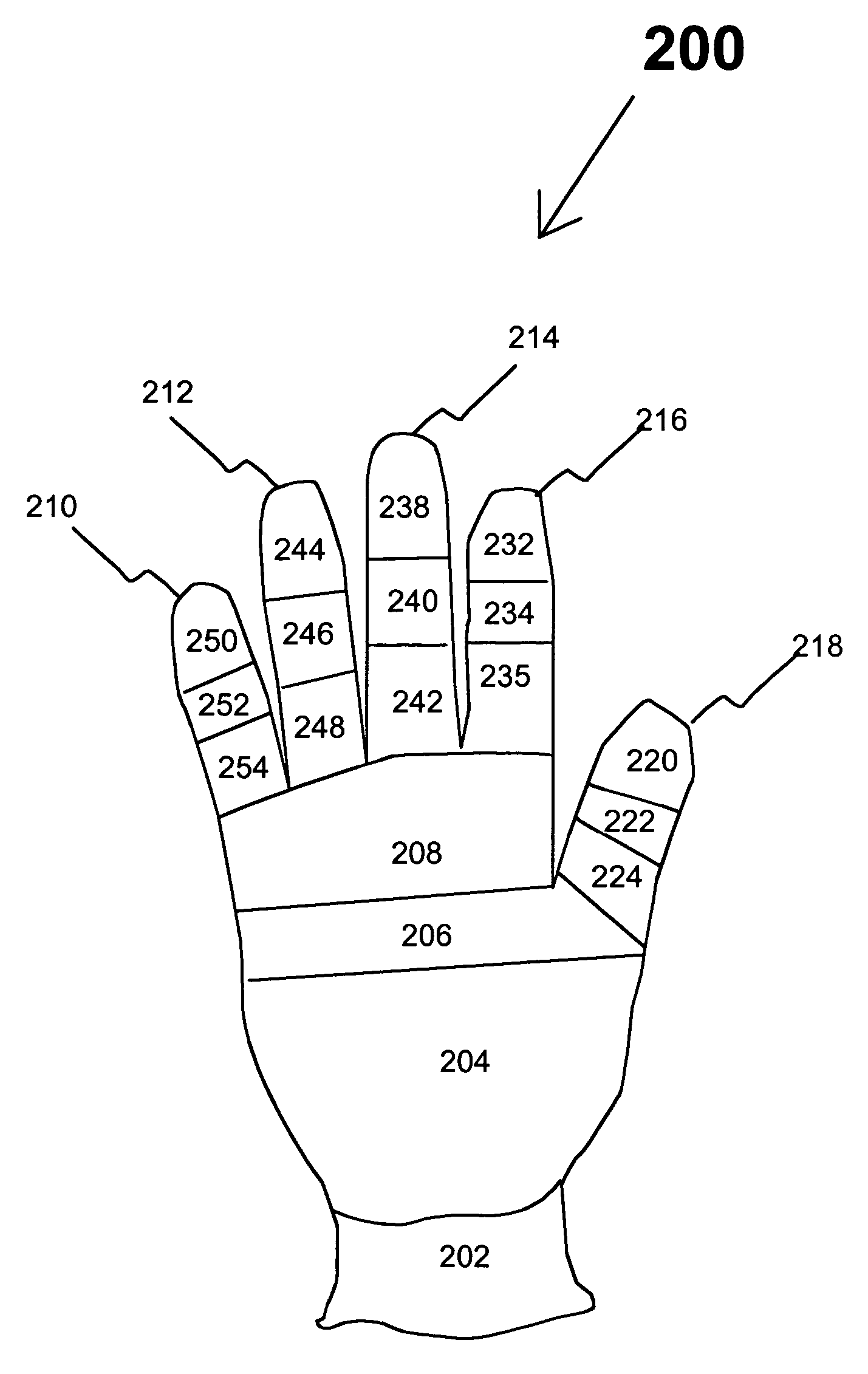
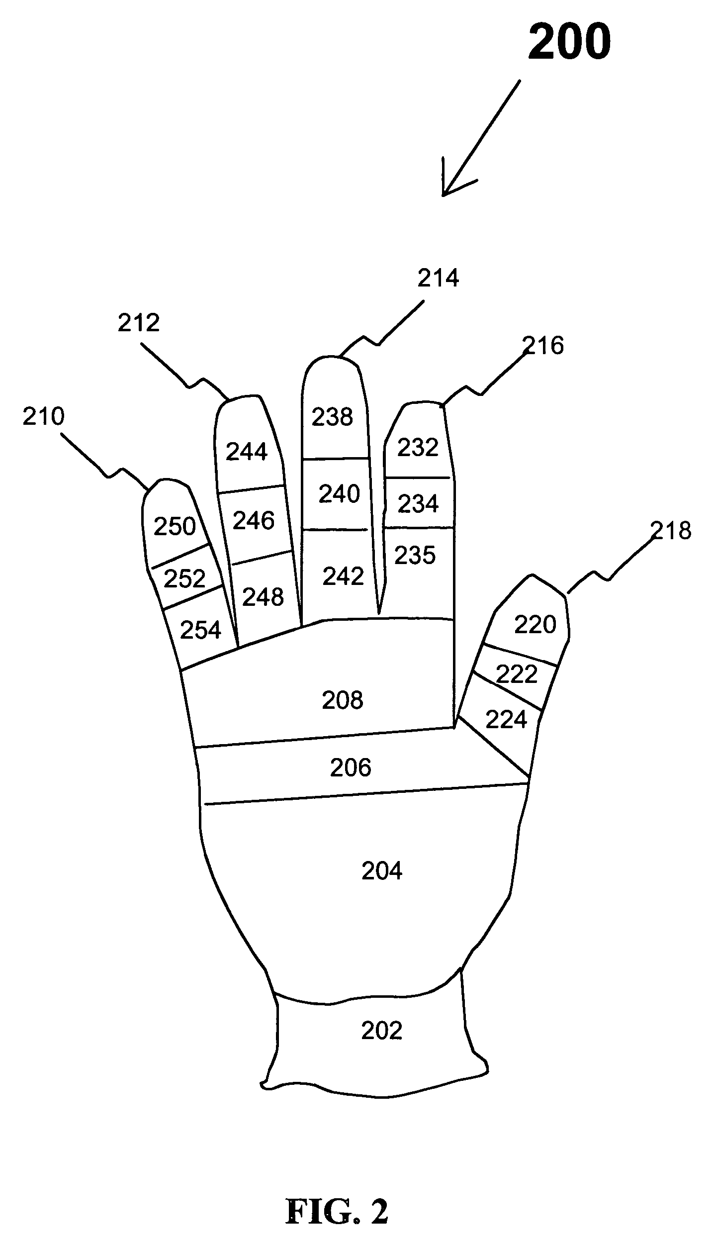
[0023]Existing flat knitting machines can be programmed to accommodate a large number of changes in stitch dimensions using stitch setup and to alter the physical dimensions used in a standard eight component glove 100 of FIG. 1. Stitch setup can be used to “customize” gloves and liners manufactured in sizes 6, 7, 8, 9, and 10. They also can be used to develop specifications for finger length and width, palm len...


PUM


Abstract

A knitted glove made by creating each of the sections of the glove using a separate knitting course on a flat knitting machine providing variable stitch dimensions. Each of these sections provides its own designed stretch characteristics so that the glove fits tightly, yet provides flexibility and ease of movement. The variable stitch dimension is achieved by 1) varying the depth of penetration of a knitting needle into a fabric being knitted by a computer program, 2) adjusting the tension of yarn between a pinch roller and a knitting head by a mechanism controlled by a computer, and 3) casting off or picking up additional stitches in a course. The glove includes a plurality of finger components made from at least ten separately knitted sections, two palm components, each of which is made from at least two separately knitted sections, and a wrist component made from at least one knitted section.

Description

[0001]This is a Continuation-In-Part of U.S. patent application Ser. No. 10 / 892,763, filed Jul. 16, 2004, now U.S. Pat. No. 6,962,064, the disclosure of which is hereby incorporated in its entirety by reference thereto.FIELD OF THE INVENTION[0002]The present invention relates to knitted gloves. More specifically; the invention relates to knitted gloves, knitted glove liners, and methods of making them.BACKGROUND OF THE INVENTION[0003]Knitted gloves are commonly used in handling and light assembly conditions. Knitted gloves used for these purposes are currently made using flat knitting machines that use a number of needles in the form of a needle array and a single yarn to knit the gloves using eight basic components to comprise the glove. These eight components include one component for each of the five fingers, two components for the palm including a upper section and a lower section, and one component for the wrist area. All of these sections are cylinders or conical sections that...

Claims


Application Information

Patent Timeline
Patent Type & Authority Patents(United States)
IPC IPC(8): D04B7/34A41D19/00A41D19/015D04B9/58
CPCA41D19/00A41D19/0065A41D19/01558D04B1/10D04B1/28D04B7/34D04B15/488A41D2500/10D10B2403/0333A41D19/02
Inventor HARDEE, FREDPLEMMONS, GREGTHOMPSONALLEN, SANNARASIMHAN, DAVE
Owner ANSELL HEALTHCARE PRODS
Why Eureka
Try Eureka