Wind load anchors and high-wind anchoring systems for cavity walls

Active Publication Date: 2010-10-14
HOHMANN & BARNARD INC
View PDF29 Cites 45 Cited by
  • Summary
  • Abstract
  • Description
  • Claims
  • Application Information

AI Technical Summary

Benefits of technology

[0044]It is another object of the present invention to provide high strength through double-walled construction.
[0045]It is yet another object of the present invention provide an anchoring system for preventing disengagement under high-wind load or other environmental conditions.
[0046]It is still yet another object of the present invention to provide an anchoring sys

Problems solved by technology

Dangerous conditions persist—tragedy strikes—change occurs.
Even with such a remarkable background, the anchoring of brick veneer to a variety of backup walls faces a dearth of standards.
The FEMA analysis of brick veneer failures modes are, in turn, categorized as human failures—used wrong fasteners; misaligned tie during installation; ties not installed;

Method used


Image

  • Wind load anchors and high-wind anchoring systems for cavity walls
  • Wind load anchors and high-wind anchoring systems for cavity walls
  • Wind load anchors and high-wind anchoring systems for cavity walls

Examples


Example

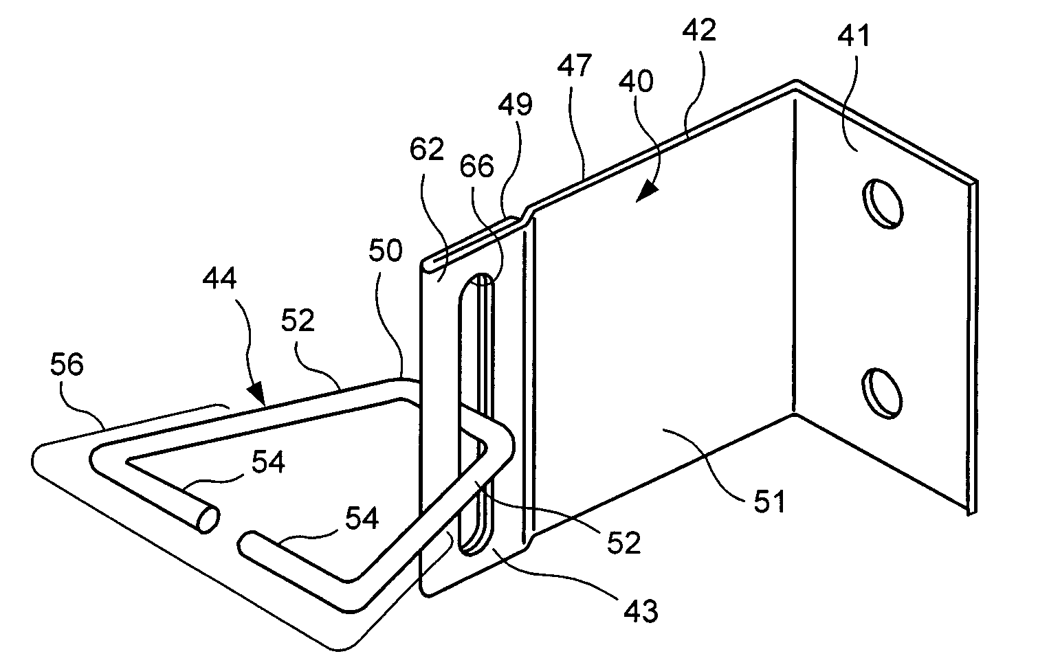
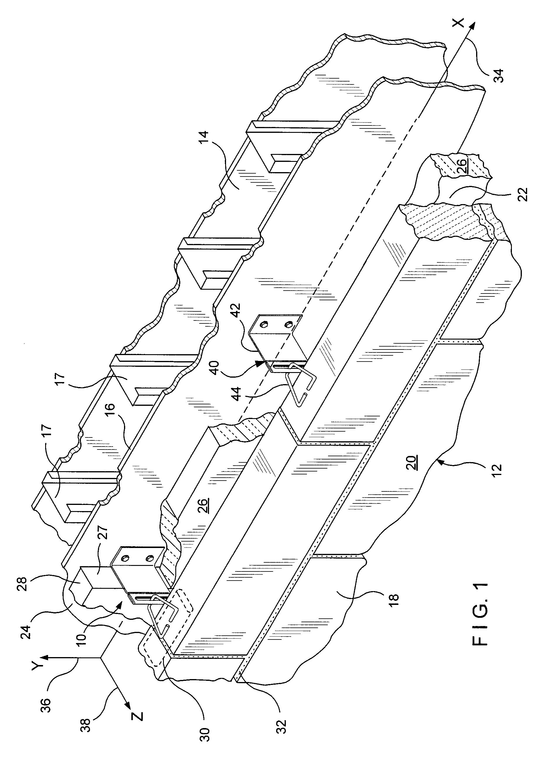
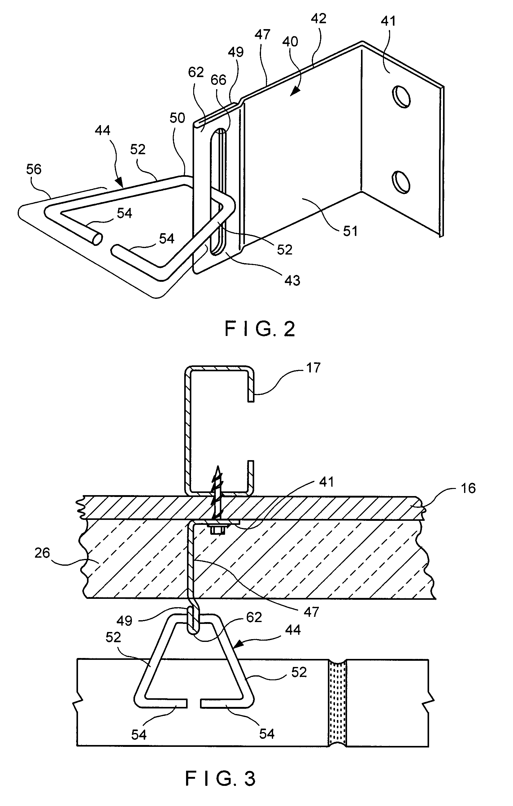
[0065]Referring now to FIGS. 1 through 4, the first embodiment shows a surface-mounted anchoring system suitable for cavity wall constructs under high-wind load conditions. The high-wind load anchoring system for cavity walls is referred to generally by the numeral 10. A cavity wall structure 12 is shown having an inner wythe or dry wall backup 14 formed from sheetrock or wallboard 16 mounted on metal studs or columns 17. The cavity wall 12 also includes an outer wythe or facing 18 of brick 20 construction. Between the inner wythe 14 and the outer wythe 18, a cavity 22 is formed. Attached to the exterior surface 24 of the inner wythe 14 is insulation in the form of insulating panels 26. The insulation 26 is disposed on wallboard 16. Seams 28 between adjacent panels of insulation 26 are substantially vertical and the vertical edges 27 thereof abut the wing of the wall anchor surface mounted at the center of a column 17. The seams 28 seat to and about the wall anchor wings, thereby ma...

Example

[0075]The description which follows is a second embodiment of the surface-mounted anchoring system for cavity walls of this invention. For ease of comprehension, wherever possible, similar parts use reference designators 100 units higher than those above. Thus, a veneer tie 144 of the second embodiment is analogous to the veneer tie 44 of the first embodiment. Referring now to FIGS. 5 through 7, the second embodiment of the surface-mounted anchoring system is shown and is referred to generally by numeral 110. As in the first embodiment, a cavity wall structure 112 is shown. The second embodiment has an inner wythe or backup wall 114 of a dry wall or a wallboard construct 116 on columns or studs 117 and an outer wythe or veneer 118 of brick 120. Here, the anchoring system includes a surface mounted wall anchor 140 with a pair of slotted, double walled wing portions 143 or receptors for receiving the veneer tie 144, and a reinforcement snap-in wire 146 which interengages with the vene...

Example

[0083]The description which follows is a third embodiment of the high-wind load anchoring system for cavity walls of this invention. This description, wherever possible, will continue the numbering convention used above wherein similar parts use reference designators 100 units higher than those in the second embodiment. Thus, the veneer tie 144 of the second embodiment is analogous to a veneer tie 244 of the third embodiment.

[0084]Referring now to FIGS. 8 through 10, the third embodiment of the surface-mounted anchoring system is shown and is referred to generally by numeral 210. An inner wythe 214 of cavity wall structure 212 has exterior spray-type insulation 226 disposed thereon, although other forms of insulation are available for use in the anchoring system. The third embodiment has an inner wythe or back-up wall 214 of masonry block 216 and an outer wythe or veneer 218 of brick 220. In this embodiment, the anchoring system has a surface mounted wall anchor 240 with a receptor ...


PUM


Abstract

High-wind load wall anchors and high-wind load wall anchoring systems for cavity walls are described which utilize double-walled anchor constructs with interengaging wire formative veneer ties. The high wind load anchors are mounted upon an interior cavity wall and the veneer ties are embedded within joints of an exterior cavity wall. The anchors have an aperture, for threading the veneer ties therethrough and restricting undesired movement, coupled with a double-walled wing structure to resist anchor deformation by high-wind forces. For resistance against seismic forces, the high-wind load wall anchoring system has a reinforcement wire which snaps into contoured veneer ties.

Description

BACKGROUND OF THE INVENTION[0001]1. Field of the Invention[0002]This invention relates to wall anchors and anchoring systems for cavity walls. More particularly, the invention relates to systems for cavity walls subjected to high-wind loading conditions.[0003]2. Description of the Prior Art[0004]Emergent conditions foster innovation. Dangerous conditions persist—tragedy strikes—change occurs. Whether it is a traffic light at a busy intersection or a less than substantial seawall facing a hurricane, society seems naturally to procrastinate.[0005]Hurricane Katrina formed Aug. 23, 2005 and reached peak strength on Aug. 28, 2005 with one-minute sustained winds of 175 mph. In December 2005, the Federal Emergency Management Agency (FEMA) issued an analysis of Attachment of Brick Veneer in High-Wind Regions. Even with such a remarkable background, the anchoring of brick veneer to a variety of backup walls faces a dearth of standards.[0006]The FEMA analysis of brick veneer failures modes ar...

Claims


Application Information

Patent Timeline
IPC IPC(8): E04B1/74E04B1/38
CPCE04B1/4178
Inventor HOHMANN, JR., RONALD P.
Owner HOHMANN & BARNARD INC
Why Eureka
Try Eureka