Zoom lens with multi-layers for illumination

Inactive Publication Date: 2014-08-07
HSU CHEN WEI
View PDF3 Cites 15 Cited by
  • Summary
  • Abstract
  • Description
  • Claims
  • Application Information

AI Technical Summary

Benefits of technology

[0004]Accordingly, the primary object of the present invention is to provide a zoom lens with multi-layers for illumination c

Problems solved by technology

However, either way is complex and would cause the production cost increasing.
Furthermore, they are only able to change the projection either distance or range due to the ways of increasing light projections.
Furth

Method used


Image

  • Zoom lens with multi-layers for illumination
  • Zoom lens with multi-layers for illumination
  • Zoom lens with multi-layers for illumination

Examples


Embodiment Construction

[0021]In order that those skilled in the art can further understand the present invention, a description will be provided in the following in details. However, these descriptions and the appended drawings are only used to cause those skilled in the art to understand the objects, features, and characteristics of the present invention, but not to be used to confine the scope and spirit of the present invention defined in the appended claims.

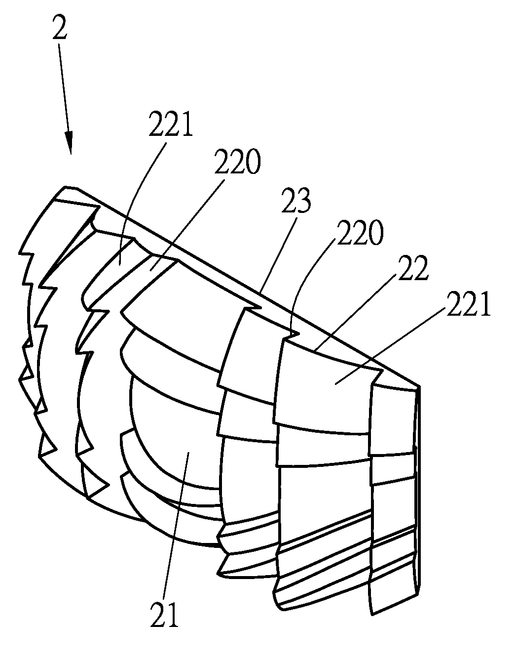
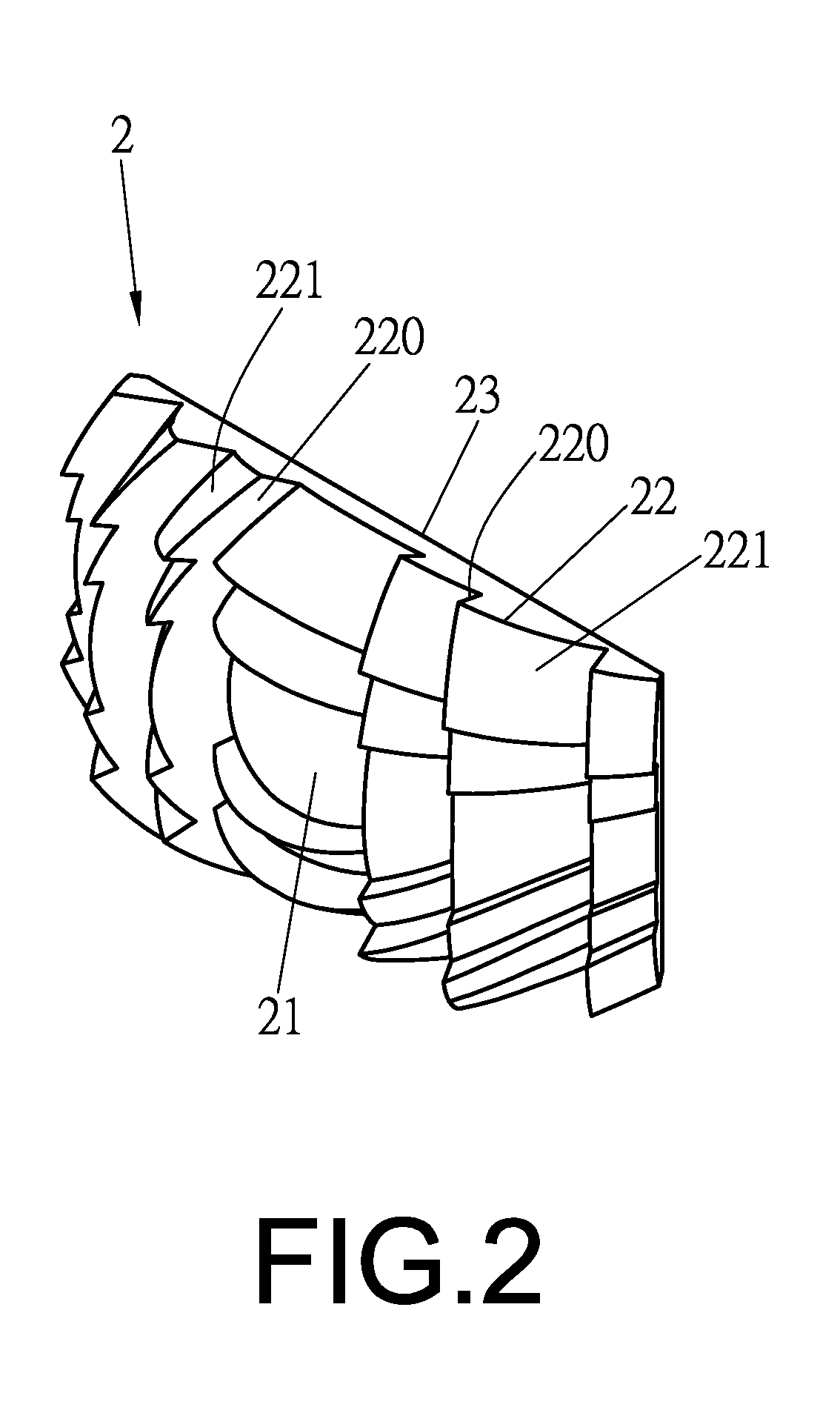
[0022]FIGS. 1 to 5 the embodiment of the zoom lens with multi-layers for illumination according to the present invention is illustrated. The zoom lens with multi-layers for illumination comprises a lens body 2. The lens body 2 has at least one free curved surface 21. The free curved surface 21 includes a plurality of zoom curved surfaces 22 with multiple layers. The zoom curved surface 22 consists of an oblique plane 220 on one side and arc surface 221 on the other side. A flat surface 23 is formed to an opposite side of the free curved surface 21 ...


PUM


Abstract

The zoom lens with multi-layers for illumination mainly comprises a lens body that has at least one free curved surface on a side. The free curved surface is designed to be multiple zoom curved surfaces with multiple layers. Besides, one side of the curved surface is designed to be oblique and the other side is arc surface. Hence, the curved surface can be divided into multiple patterns with multiple focuses through the various combinations of complex free curved surfaces. Furthermore, the control of the luminance and projection angle can be achieved by the various combinations of zooming and focusing on the curved surfaces,

Description

FIELD OF THE INVENTION[0001]The present invention relates to zoom lens with multi-layers for illumination, particularly the zoom lens with plurality of curved surfaces able to modify the luminance and the angle of the light projection and to reduce the thickness and the area of the lens. Hence, it is able to reduce the production cost, to improve the light projection distance and range and luminance level and to control of light projection angles.DESCRIPTION OF THE PRIOR ART[0002]Commonly, LED has been used to replace most of the bulbs, such as vehicle lamp, street lamp, flashlight and searchlight for friendly environmental purpose. However, the projection area of LED is smaller as shown in FIG. 1. In order to enhance the luminance and the projection area of the lighting devices, either a hemispheric lens 11 is arranged in front of a LED 10 and a light reflector 12 is disposed along LED 10, or, the numbers of LED are increased. However, either way is complex and would cause the prod...

Claims


Application Information

Patent Timeline
IPC IPC(8): F21V5/04
CPCF21V5/04F21V5/045F21Y2115/10F21S41/143F21S41/265F21S43/14F21S43/26G02B3/08
Inventor HSU, CHEN-WEI
Owner HSU CHEN WEI
Why Eureka
Try Eureka