System and method for continuous casting

a continuous casting and belt technology, applied in the direction of belts, metal processing, metal processing, etc., can solve the problems of limiting casting speed, affecting metallurgical quality, and the most unstable belt, so as to improve the metallurgical quality, including surface quality, of the cast strip, and improve heat transfer rate

Active Publication Date: 2018-10-11
HAZELETT STRIP CASTING CORP US
View PDF4 Cites 0 Cited by
  • Summary
  • Abstract
  • Description
  • Claims
  • Application Information

AI Technical Summary

Benefits of technology

[0010]It is another object of the present invention to provide a twin belt continuous casting apparatus that improves heat transfer rates throughout the thickness of the cast strip as compared to existing apparatuses.
[0011]It is another object of the present invention to provide a twin belt continuous casting apparatus that produces thinner metal strips than has heretofore been possible.
[0012]It is another object of the present invention to provide a twin belt continuous casting apparatus that improves metallurgical quality, including surface quality, of the cast strip.
[0013]It is another object of the present invention to provide a twin belt continuous casting apparatus that facilitates the use of thicker belts than has heretofore been possible.
[0014]It is another object of the present invention to provide a method for twin belt continuous casting that minimizes belt take-off.
[0015]It is another object of the present invention to provide a method for twin belt continuous casting that enables the production of strips less than about 7 millimeters in thickness.

Problems solved by technology

For example, with twin roll casting, where metal is cast against the opposed nip rolls, the length of the mold is limited to a short distance prior to the tangent point of the opposed rolls, the diameters of which are limited by practical considerations such as the space that must be made available for the feeding apparatus.
These upper limits on the diameter and circumference of the rolls limits casting speed, roll life and metallurgical quality.
Although the belts allow for an extended mold length as compared to twin roll casting, initial solidification occurs in the zone immediately following the nip, where the belts are the most unstable.
As will be readily appreciated, metallurgical quality may be negatively impacted in regions of belt instability, such as in this zone immediately following the nip, particularly when casting alloys having broad freezing ranges.
Accordingly, additional post-casting operations such as rolling are often required to achieve thicknesses less than 15 millimeters, which increases overall cost.
In addition, the solidification of the internal layers of these relatively thick cast sections is slowed considerably by the thermal resistance of the surface layers, which can be particularly detrimental when casting alloys having a broad freezing range.

Method used


Image

  • System and method for continuous casting
  • System and method for continuous casting
  • System and method for continuous casting

Examples


Embodiment Construction

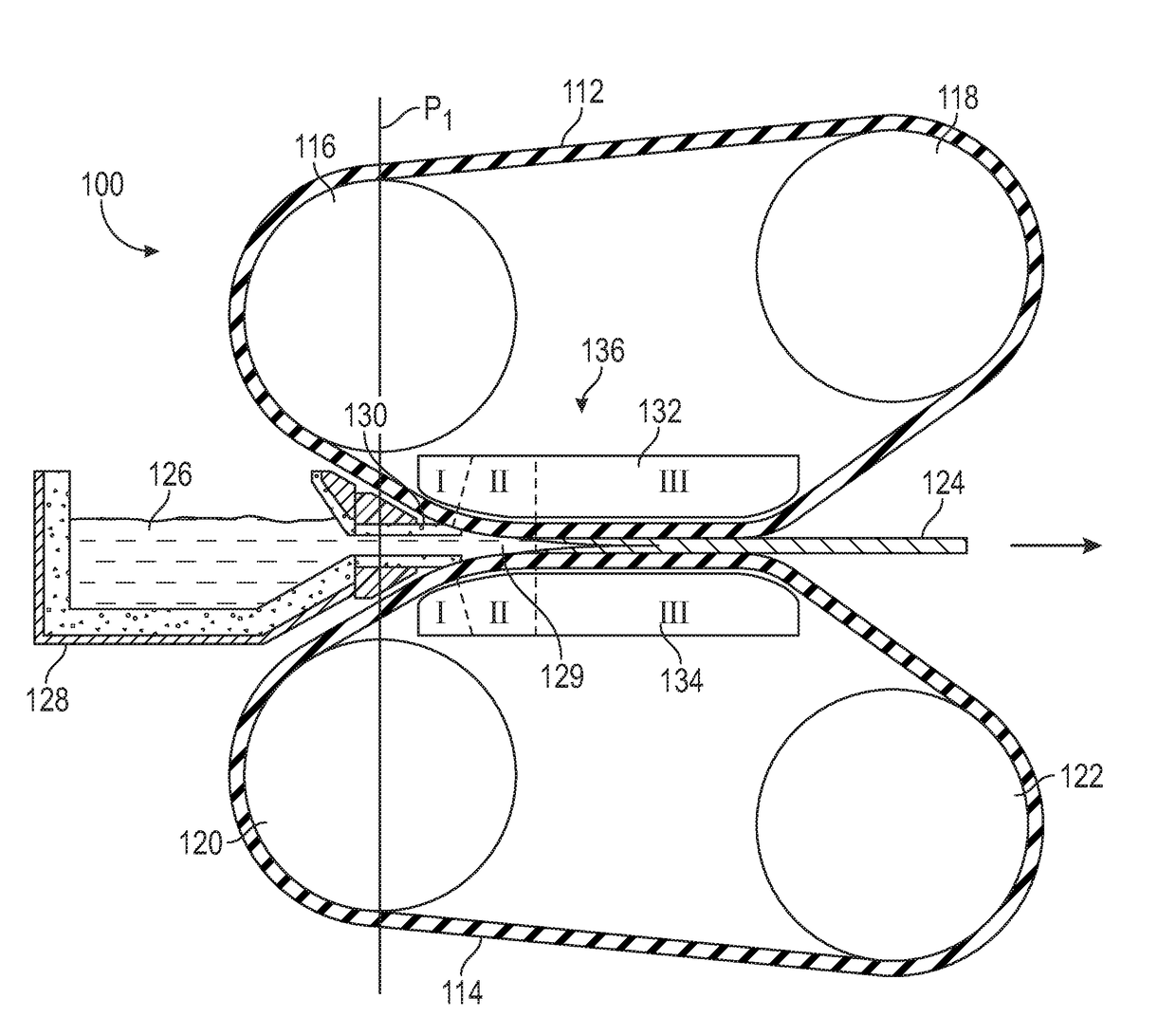
[0026]Referring to FIG. 3, a twin belt casting apparatus 100 according to an embodiment of the present invention is illustrated. As shown therein, the casting apparatus 100 includes a first endless belt 112 carried by a first upstream pulley or roll 116 and a first downstream pulley or roll 118, and a second endless belt 114 carried by a second upstream pulley or roll 120 and a second downstream pulley or roll 122. Each roll is mounted for rotation about its longitudinal axis and serves to rotate, guide and / or tension the belts 112, 114. Either or both of the upper rolls 116, 118 and the lower rolls 120, 122 may be driven by a suitable motor (not shown). The belts 112, 114 are endless and are preferably formed of a metal which has low reactivity or is non-reactive with the metal being cast. As illustrated in FIG. 3, the upstream rolls 116, 120 are positioned one above the other, some distance apart to allow room for a metal feeding apparatus 128 to be positioned in the space, and de...


PUM

PropertyMeasurementUnit
radiusaaaaaaaaaa
radiusaaaaaaaaaa
thicknessaaaaaaaaaa

Abstract

A continuous casting apparatus includes a first belt carried by a first upstream pulley and a first downstream pulley, a second belt carried by a second upstream pulley and a second downstream pulley, and a mold region defined by a first mold support section arranged behind the first belt and a second mold support section arranged behind the second belt. The first mold support section supports the first belt and defines a shape of the first belt in the mold region and the second mold support section supports the second belt and defines a shape of the second belt in the mold region. At least one of the first mold support section and the second mold support section includes a transition portion and a generally planar portion downstream from the transition portion. The transition portion has a variable radius configured to receive molten metal from a metal feeding device.

Description

CROSS-REFERENCE TO RELATED APPLICATIONS[0001]This application claims the benefit of U.S. Provisional Application Ser. No. 62 / 483,987, filed on Apr. 11, 2017, which is hereby incorporated by reference herein in its entirety.FIELD OF THE INVENTION[0002]The present invention relates generally to continuous casting of metals and, more particularly, to a twin belt casting system and method for continuous casting of metals.BACKGROUND OF THE INVENTION[0003]Continuous casting of light metal alloys such as, for example, aluminum alloys, has typically been performed in continuous casters, such as twin roll casters and twin belt casters. Twin roll casters generally include a pair of opposed, rotating rolls against which molten metal is fed. The centerlines of the rolls are in a vertical or generally vertical plane that passes though a region of minimum clearance between the rolls, referred to as the “nip”, such that the cast strip forms in a generally horizontal path, although other twin roll ...

Claims


Application Information

Patent Timeline
Patent Type & Authority Applications(United States)
IPC IPC(8): B22D11/06
CPCB22D11/0654B22D11/0605B22D11/0677
Inventor DYKES, CHARLES DKAGAN, VALERY GHAMILTON, DOUGLAS ADAVIS, CASEY JPENNUCCI, JOHN E
Owner HAZELETT STRIP CASTING CORP US
Why Eureka
Try Eureka