

Tabbed transfer fins for air-cooled heat exchanger
a technology of heat exchangers and transfer fins, which is applied in the field of heat exchangers to achieve the effects of increasing pressure drop, facilitating uniform flow, and enhancing heat transfer
- Summary
- Abstract
- Description
- Claims
- Application Information
AI Technical Summary
Benefits of technology
Problems solved by technology
Method used
Image

Examples
Embodiment Construction
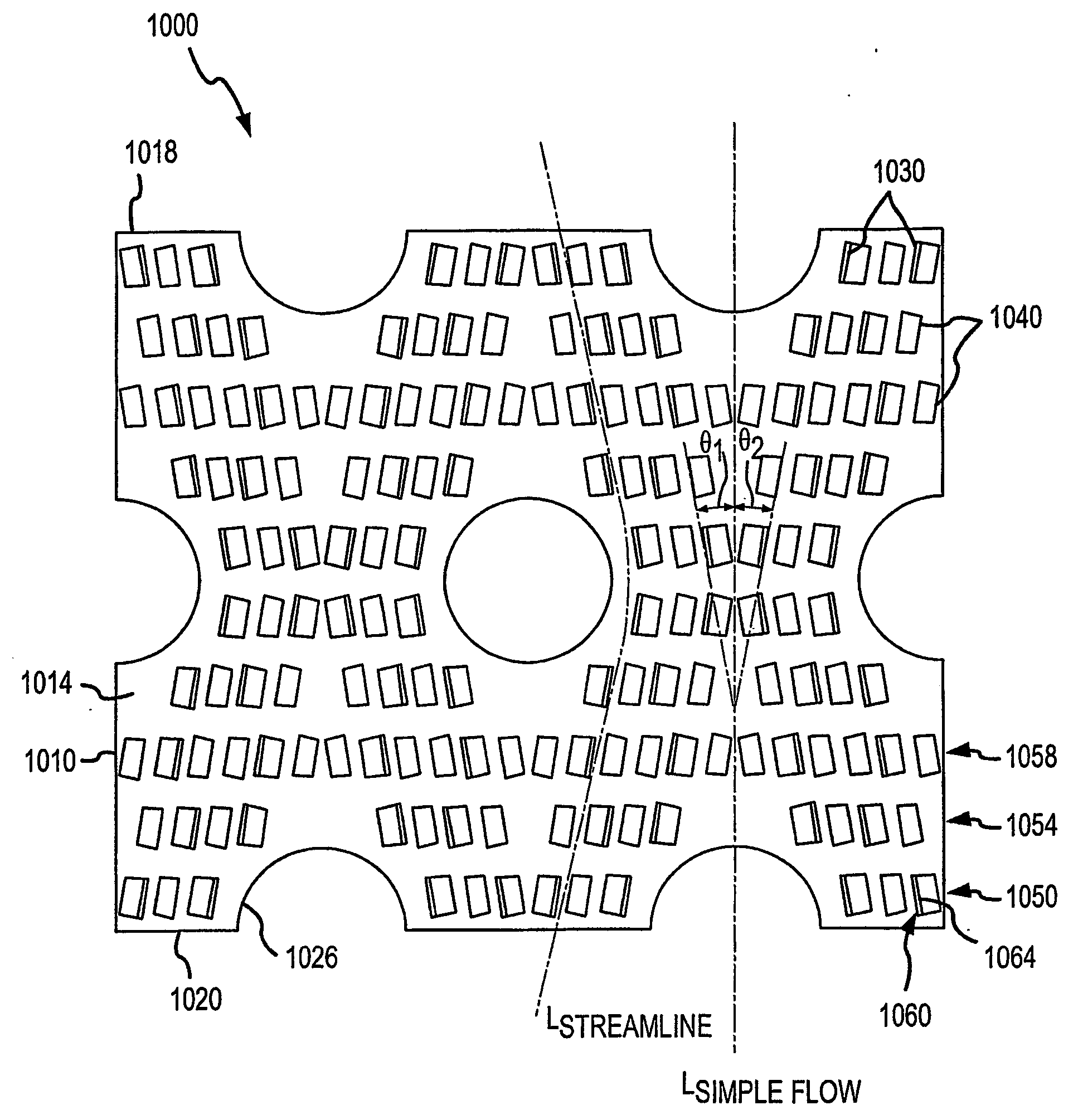
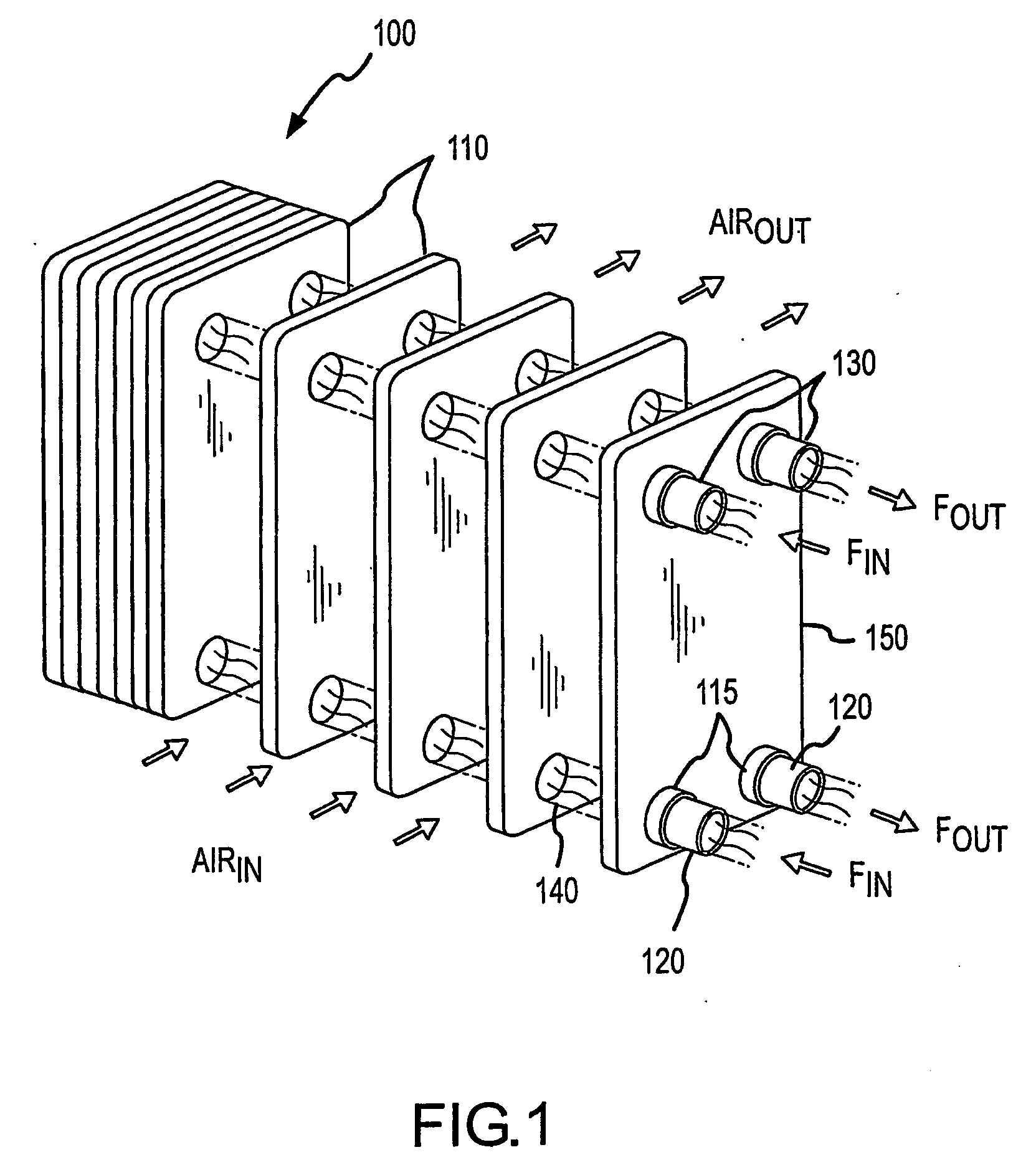
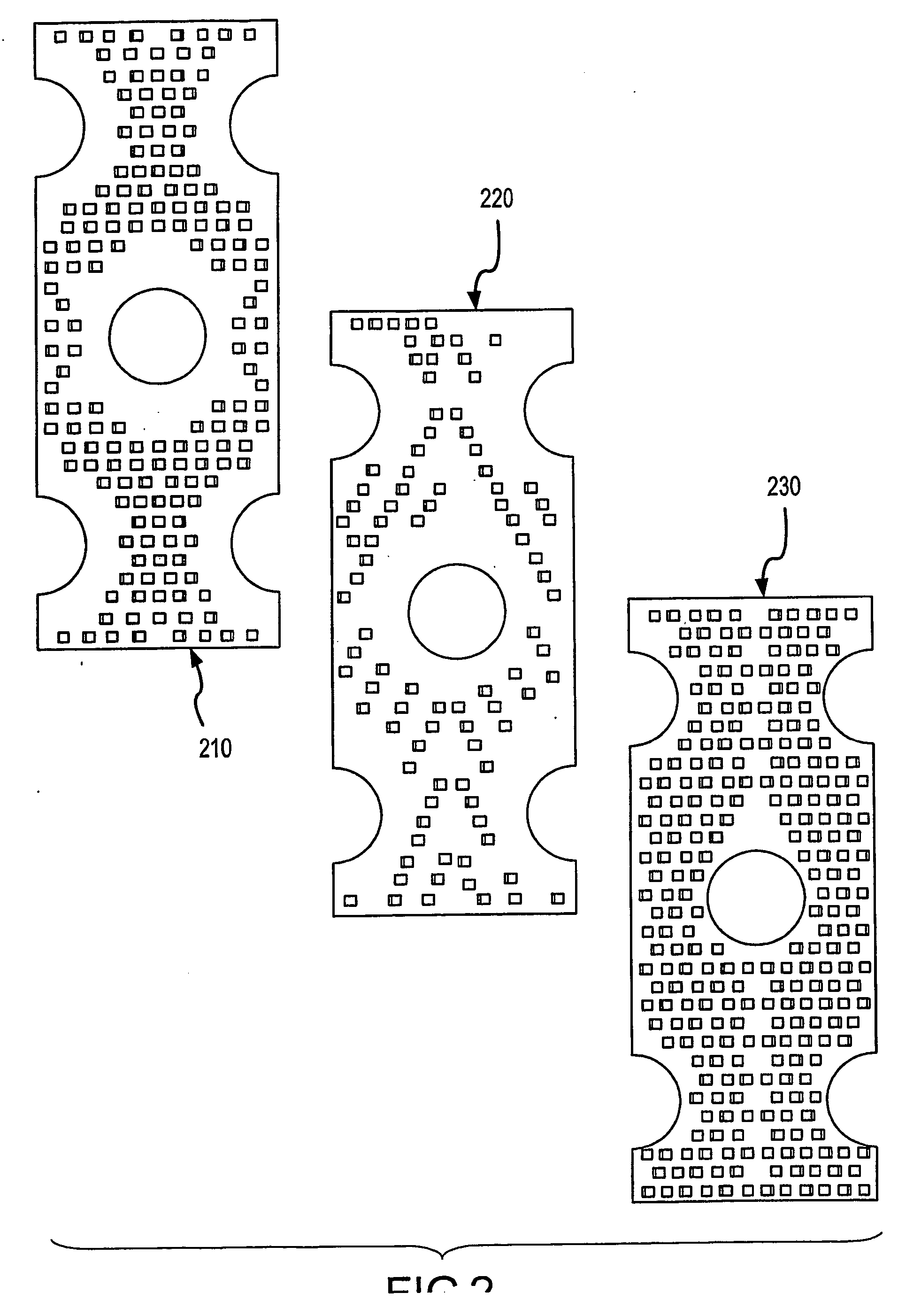
[0036] The present invention is directed to heat exchanger fins employing tabs to increase heat transfer effectiveness, heat exchangers or condensers incorporating such tabbed fins or plates such as air-cooled, finned-tube heat exchangers, and methods of making tabbed fins. Generally, each fin of the invention includes a multiplicity of small tabs or secondary fins that are formed by punching material (i.e., metal) out of the main fin body (i.e., creating a hole or opening) and the punched material is bent outward away from the main fin body in one or both directions from the surface of the fin. To minimize or control the creation of a vortex or increased pressure drop, the tabs are generally planar and aligned with the direction of the fluid, e.g., air, flowing over the fins in the channel between adjacent fins. In other words, a leading edge of the tab first contacts the flowing gas and the substantially planar body of the tab is aligned substantially parallel to the gas flow path...
PUM
| Property | Measurement | Unit |
|---|---|---|
| angle | aaaaa | aaaaa |
| angle | aaaaa | aaaaa |
| bend angle | aaaaa | aaaaa |
Abstract
Description
Claims
Application Information