Heat exchanger fin, heat exchanger, condensers, and evaporators

a heat exchanger and fin technology, applied in the direction of indirect heat exchangers, refrigeration components, light and heating apparatus, etc., can solve problems such as deterioration of heat transfer rate, and achieve the effect of preventing the generation of bypass flow and improving heat transfer ra

Inactive Publication Date: 2007-03-08
SHOWA DENKO KK
View PDF7 Cites 27 Cited by
  • Summary
  • Abstract
  • Description
  • Claims
  • Application Information

AI Technical Summary

Benefits of technology

[0090] In the evaporator according to the invention, in the same manner as mentioned above, the heat medium such as air will be assuredly introduced in between louvers to flow smoothly along each louver, enabling improvement of the heat transfer rate by preventing generation of bypass flow.

Problems solved by technology

However, the smaller louver pitch may cause clogging of sand and / or bridging of condensed water between the adjacent louvers 51, preventing the air A passing through the air passage 60 from being introduced into the louver gaps each formed between the adjacent louvers 51.
This causes the bypass flow of the air A, i.e., the air flow passing through the fin spaces each formed between the adjacent louver fins 50 without being introduced into the louver gaps, resulting in a deterioration of the heat transfer rate.

Method used


Image

  • Heat exchanger fin, heat exchanger, condensers, and evaporators
  • Heat exchanger fin, heat exchanger, condensers, and evaporators
  • Heat exchanger fin, heat exchanger, condensers, and evaporators

Examples


examples

[0144] Hereinafter, Examples related to the present invention and Comparative Examples which deviate from the gist of the present invention will be explained.

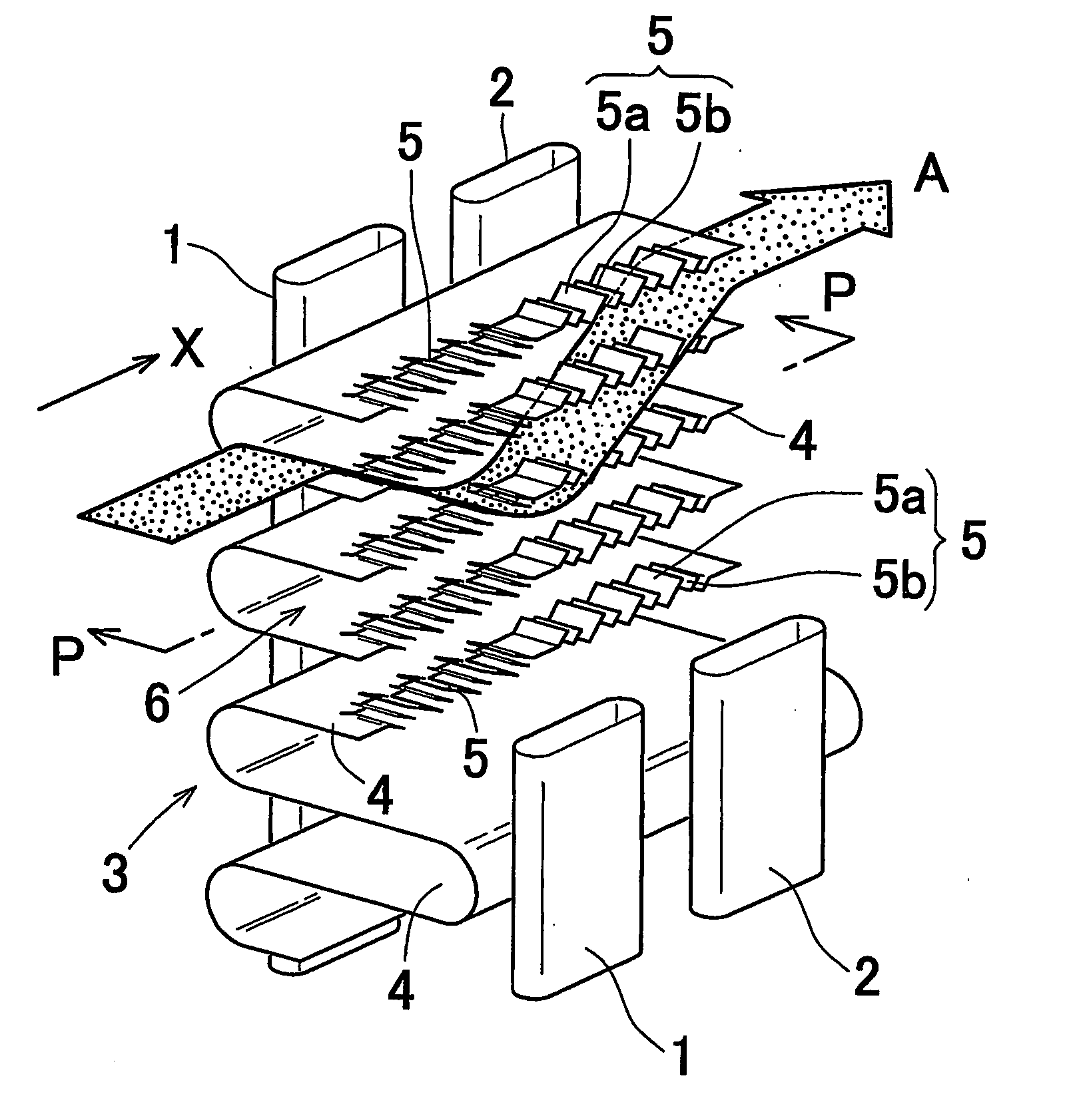
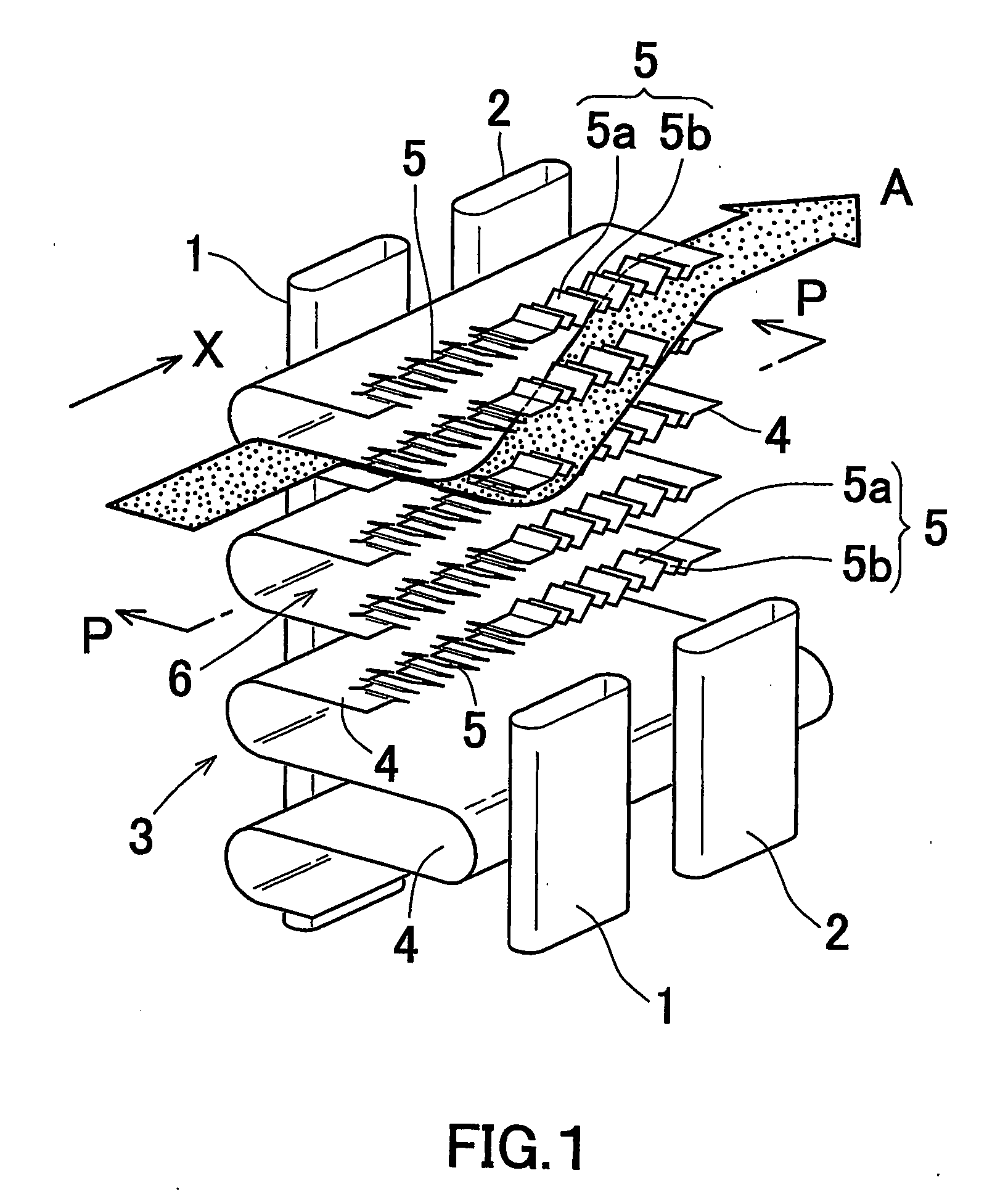
[0145] In accordance with the aforementioned embodiment, evaporators for car air-conditioners in which corrugated fins with different kinds of louvers were arranged between the adjacent flat heat exchanging tubes were examined.

examples 1 to 5

[0146]

TABLE 1Lwl (mm)Lws (mm)Lws / LwlFp (mm)La (°)Example 11.10.1670.1521.326Example 21.00.3330.3331.326Example 31.00.500.501.326Example 40.850.5830.6861.326Example 50.850.650.7651.326Comparative0.750.751.01.326Example 1

Lwl: width of wide louver (mm)

Lws: width of narrow louver (mm)

Lws / Lwl: louver width ratio

Fp: fin pitch (mm)

La: louver angle (°)

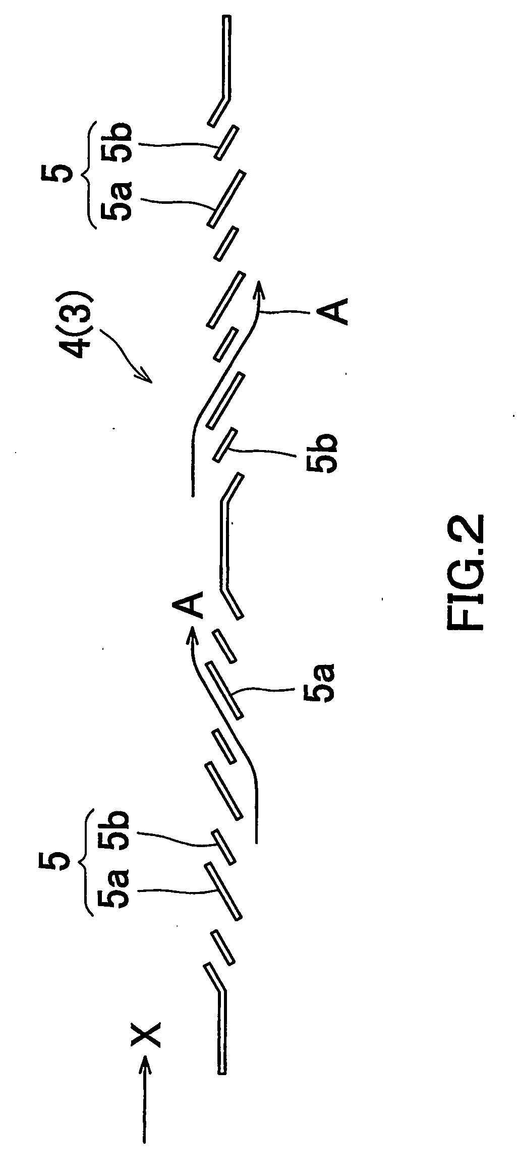
[0147] In Table 1, the evaporator of Example 1 was provided with corrugated fins having a plurality of louver fins each including wide louvers and narrow louvers arranged alternatively. The louver width Lwl of the wide louver was 1.1 mm, the louver width Lws of the narrow louver was 0.167 mm, the louver angle La was 26°, the fin pitch Fp was 1.3 mm and the louver width ratio Lws / Lwl was 0.152.

[0148] In the evaporator of Example 2, the louver width Lwl of the wide louver was set to 1.0 mm, and the louver width Lws of the narrow louver was set to 0.333 mm. The remaining dimensions were set to the same as those in Example 1. The louver widt...

examples 6 , 7

Examples 6, 7

[0157]

TABLE 2Lwl (mm)Lws (mm)Lws / LwlFp (mm)La (°)Example 61.00.3330.3331.328Example 71.00.500.501.328Comparative0.750.751.01.328Example 2

Lwl: width of wide louver (mm)

Lws: width of narrow louver (mm)

Lws / Lwl: louver width ratio

Fp: fin pitch (mm)

La: louver angle (°)

[0158] As shown in Table 2, the evaporator of Example 6 was prepared in the same manner as the aforementioned Example 2 except that the louver angle La was set to 28°.

[0159] The evaporator of Example 7 was prepared in the same manner as the aforementioned Example 3 except that the louver angle La was set to 28°.

[0160] The evaporator of Comparative Example 2 was prepared in the same manner as the aforementioned Comparative Example 1 except that the louver angle La was set to 28°.

[0161] Regarding the aforementioned evaporators, each heat transfer rate with respect to the front wind velocity was measured by computer simulation. The results are shown in the graph of FIG. 6.

[0162] As will be apparent from t...


PUM

PropertyMeasurementUnit
angleaaaaaaaaaa
distanceaaaaaaaaaa
velocityaaaaaaaaaa

Abstract

A heat exchanger fin, capable of improving heat transfer rate while preventing generation of heat bypass flow, such as a louver fin provided with a plurality louvers arranged at certain intervals in the introduction direction of air. The louvers are formed by cutting and bending the heat exchanger fin so that the air is passed while being guided by the louvers. The plurality of louvers include louvers different in louver width, the louver width being defined by a length of the louver along which the heat medium passes. Wider louvers and narrower louvers can be arranged alternatively.

Description

[0001] Priority is claimed to Japanese Patent Application No. 2003-140400 filed on May 19, 2003, and U.S. Provisional Application No. 60 / 478,360 filed on Jun. 16, 2003, the disclosure of which are incorporated by reference in their entireties. CROSS REFERENCE TO RELATED APPLICATIONS [0002] This application is an application filed under 35 U.S.C. § 111(a) claiming the benefit pursuant to 35 U.S.C. § 119(e) (1) of the filing date of Provisional Application No. 60 / 478,360 filed on Jun. 16, 2003 pursuant to 35 U.S.C. § 111 (b). TECHNICAL FIELD [0003] The present invention relates to a heat exchanger such as a car air-conditioning condenser or evaporator for use in car air-conditioning refrigeration cycles as a car air-conditioning apparatus for example. It also relates to a fin for use in heat exchangers (hereinafter referred to as “heat exchanger fin”) such as a louver fin or a corrugated fin to be equipped to the aforementioned apparatuses. BACKGROUND ART [0004] A heat exchanger such ...

Claims


Application Information

Patent Timeline
Patent Type & Authority Applications(United States)
IPC IPC(8): F28D1/04F25B39/04F25B39/02B21D53/06
CPCF28F1/128Y10T29/4938F28F2215/04
Inventor YAMAUCHI, SHINOBU
Owner SHOWA DENKO KK
Why Eureka
Try Eureka