Power battery composite heat management system and method thereof

A thermal management system, power battery technology, applied in the direction of secondary batteries, circuits, electrical components, etc., can solve the problems of not considering heat recycling, low thermal conductivity of air, poor thermal conductivity of phase change materials, etc., to avoid battery safety problems , high thermal conductivity, offset the effect of temperature rise

Active Publication Date: 2016-06-01
SOUTH CHINA UNIV OF TECH
View PDF9 Cites 28 Cited by
  • Summary
  • Abstract
  • Description
  • Claims
  • Application Information

AI Technical Summary

Problems solved by technology

[0003] At present, the thermal management technologies that have been applied include air cooling and liquid cooling, but both of them have insurmountable deficiencies, such as the low thermal conductivity of air, and the sealing and overweight of liquid cooling.
Although the thermal management technology based on phase change material cooling has certain advantages, the phase change material has poor thermal conductivity and low heat storage rate.
In addition, most current thermal management system designs do not consider the recycling of heat

Method used


Image

  • Power battery composite heat management system and method thereof
  • Power battery composite heat management system and method thereof
  • Power battery composite heat management system and method thereof

Examples


Embodiment

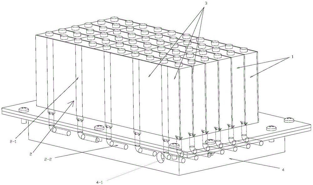
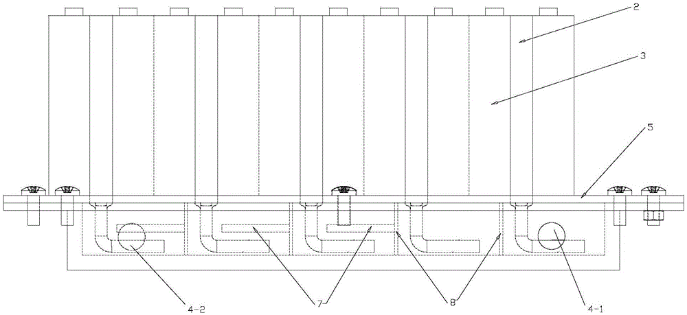
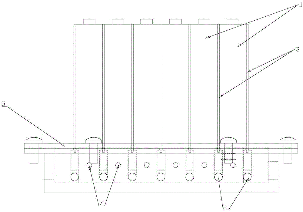
[0031] as the picture shows. The invention discloses a composite heat management system for a power battery, comprising a water tank 4 filled with a circulating fluid (the material is an aluminum alloy with light weight and low thermal conductivity), a circulating pump for driving the circulating fluid to flow, and a sealing cover plate of the water tank 4 5. A battery pack array composed of multiple single cells 1 fixedly installed on the top of the sealing cover 5; a uniform temperature plate 3 (thickness 3-5 mm) and a heat pipe 2 are pasted on the surface of each single cell 1 , there is a gap in the middle of the vapor chamber 3, the evaporation section 2-1 of the heat pipe 2 (copper powder sintered type, thickness 2-5mm) is flat, and placed in the gap, the evaporation section 2-1 passes through the The gap and the surface of the single battery 1 are attached to each other; the cooling section 2-2 of the heat pipe 2 passes through the sealing cover plate 5 and is placed in...


PUM


Abstract

The invention discloses a power battery composite heat management system and a method thereof. The power battery composite heat management system comprises a water tank filled with a circulating fluid, a circulating pump, a sealing cover plate of the water tank, and a battery pack array which is fixedly mounted above the sealing cover plate and is composed of a plurality of battery cells, wherein a temperature equalizing plate and a heat pipe are adhered onto the surface of each battery cell respectively, and cooing sections of the heat pipes pass through the sealing cover plate to be arranged in the circulating fluid in the water tank; a circulating fluid inlet is formed in one side end of the water tank, a circulating fluid outlet is formed in the other side end of the water tank, and a circulating fluid turbulent flow structure is arranged inside the water tank, so that the circulating fluid flows into the circulating fluid outlet from the circulating fluid inlet of the water tank in a curve flowing manner. The system and the method thereof can solve the technical problems such as heat dissipation, battery pack temperature difference reduction, battery preheating and heat cyclic utilization under different working conditions of batteries; and meanwhile, the system is compact and simple in structure and convenient in installation and maintenance, accords with the development tendency of battery heat management systems and electric automobiles, and has good application prospects.

Description

technical field [0001] The invention relates to a power battery protection device, in particular to a power battery composite heat management system and a method thereof. Background technique [0002] As energy issues and environmental pollution issues become more and more prominent, human beings' demand for environmental protection and energy saving is becoming stronger and stronger. Electric vehicles and hybrid vehicles driven by power batteries will surely become the mainstream of the automotive industry. my country has announced a series of favorable policies to promote the research and development of new energy vehicles, and achieved certain results. However, the power battery, the core component of an electric vehicle, generates a large amount of heat during charging and discharging, causing the battery temperature to rise. High temperature causes battery performance to degrade or even explode, and the battery temperature is too low to work in a low temperature enviro...

Claims


Application Information

Patent Timeline
Patent Type & Authority Applications(China)
IPC IPC(8): H01M10/6552H01M10/6567H01M10/613H01M10/625
CPCH01M10/613H01M10/625H01M10/6552H01M10/6567Y02E60/10
Inventor 甘云华梁嘉林李勇
Owner SOUTH CHINA UNIV OF TECH
Why Eureka
Try Eureka