
Head worn computer display systems

a display system and head technology, applied in the field of seethrough computer display systems, can solve the problems of reducing the sharpness and contrast of the displayed image, adversely affecting the seethrough view of the environment, etc., and achieves the effects of high thermal conductivity, high thermal conductivity, and promoting heat dissipation to the environmen

Active Publication Date: 2016-08-25
OSTERHOUT GROUP INC
View PDF1 Cites 162 Cited by
  • Summary
  • Abstract
  • Description
  • Claims
  • Application Information

AI Technical Summary

Benefits of technology

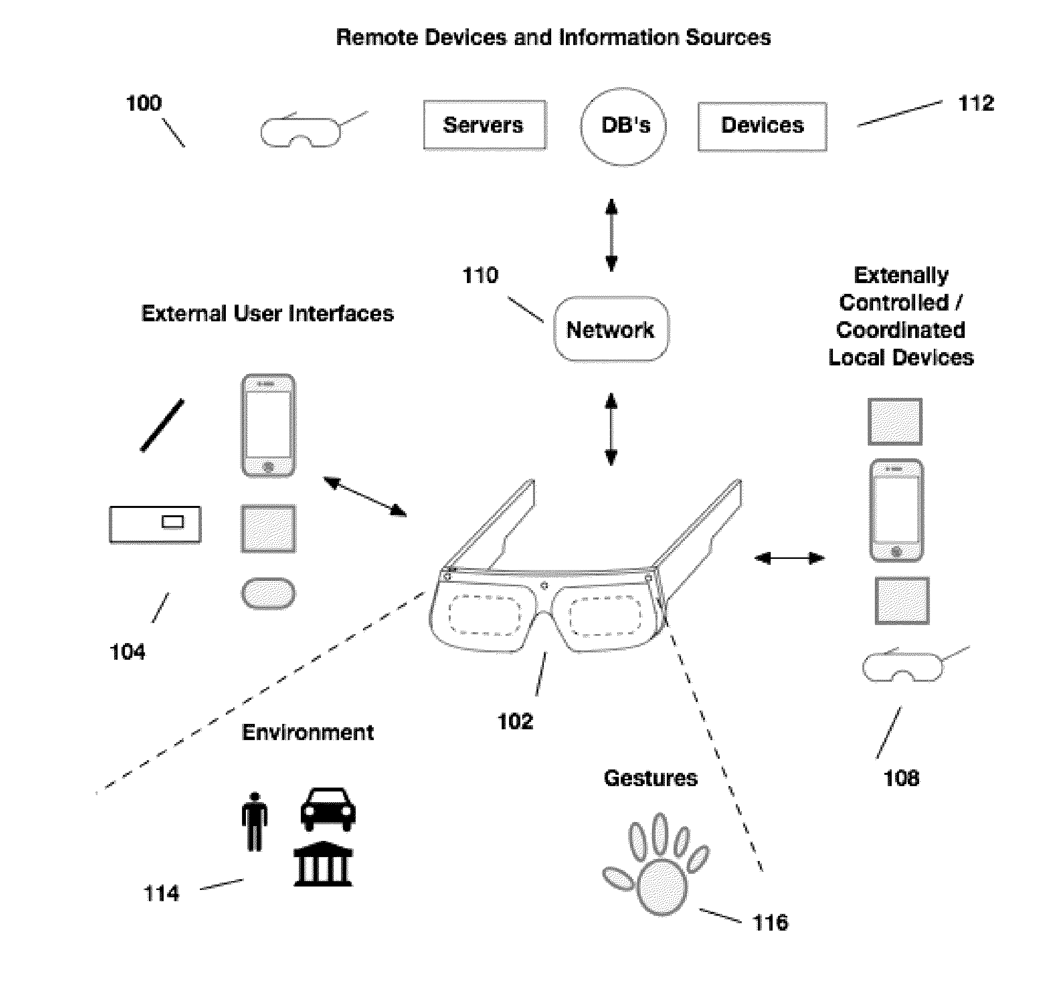
The present invention relates to methods and systems for see-through computer display systems. The invention includes an imaging and display module for a head-worn computer that provides displayed images to a user. The module includes a plurality of optical components and electrical components that are mounted to a rigid chassis with high thermal conductivity sections. The chassis is designed to align the optical components with the user's eyes and the electrical components. The module can be mounted into a frame, mask, helmet, visor, kiosk, or viewing station. The invention also includes a see-through combiner that reflects the optical components' image light towards the user's eye. The head-worn computer may also include an arm with a battery compartment and a wire connected to the image sources. The invention further includes an outer lens that is user replaceable and an optical chassis made of magnesium or aluminum. The technical effects of the invention include improved optical alignment, reduced heat dissipation, and improved user experience.

Problems solved by technology

This stray light reduces the sharpness and contrast of the displayed image in the HMD.
In addition, the stray light causes the black areas of the displayed image to be gray and this effect adversely affects the see-through view of the environment because the see-through view is produced by the combination of the light from the environment and the light from the displayed image, which is in the best case the black portions of displayed image.

Method used


Image

  • Head worn computer display systems
  • Head worn computer display systems
  • Head worn computer display systems

Examples


example 1

[0457]For a 26 deg display field of view and a 1280 pixel horizontally wide image, a pixel occupies 0.020 deg within the display field of view. If the frame rate of the full color images is 60 Hz, with three color sequential subframes images, the subframe time is 0.006 sec. The rotational speed of the head mounted display needed to produce one pixel of color breakup is then 3.6 deg / sec. If the number of horizontal pixels in the display field of view is reduced to 640 pixels and simultaneously the frame rate of the full color images is increased to 120 Hz, with three color sequential subframes images, the subframe time is reduced to 0.003, the size of a pixel is increased to 0.041 deg and the rotational speed to produce one pixel of color breakup is 14.6 deg / sec.

example 2

[0458]For a 26 deg display field of view and a 1280 pixel horizontally wide image, a pixel is 0.020 deg within the display field of view. If the smallest size that the user can detect for color breakup is one pixel wide, then a rotational speed of over 3.6 deg / sec is required if the subframe rate is 180 Hz, before color breakup is detected by the user. Even though the color breakup is an analog effect, the user's eye does not have the resolution to detect the color fringes that are present during movement below this speed. So below this rotational speed, color breakup management is not required.

example 3

[0459]For a 26 deg display field of view and a 1280 pixel horizontally wide image, a pixel is 0.020 deg within the display field of view. If the user can detect color breakup as small as one pixel wide, then a rotational speed of 3.6 deg / sec will require a shift of the subframes relative to each other of one pixel if the subframe rate is 180 Hz, to align the subframes so that color breakup is not visible to the user. If the user rotates their head at 15 deg / sec, then the subframes will require a shift of 4 pixels relative to one another to align the subframes so that color breakup is not visible. If the image frame begins with the display of the red subframe image, then no digital shifting is required for the red subframe image. A 4 pixel shift is required for the green subframe image. And, an 8 pixel shift is required for the blue subframe image. The next red subframe associated with the next image frame would then be effectively shifted 12 pixels relative to the previous red subfr...


PUM


Abstract

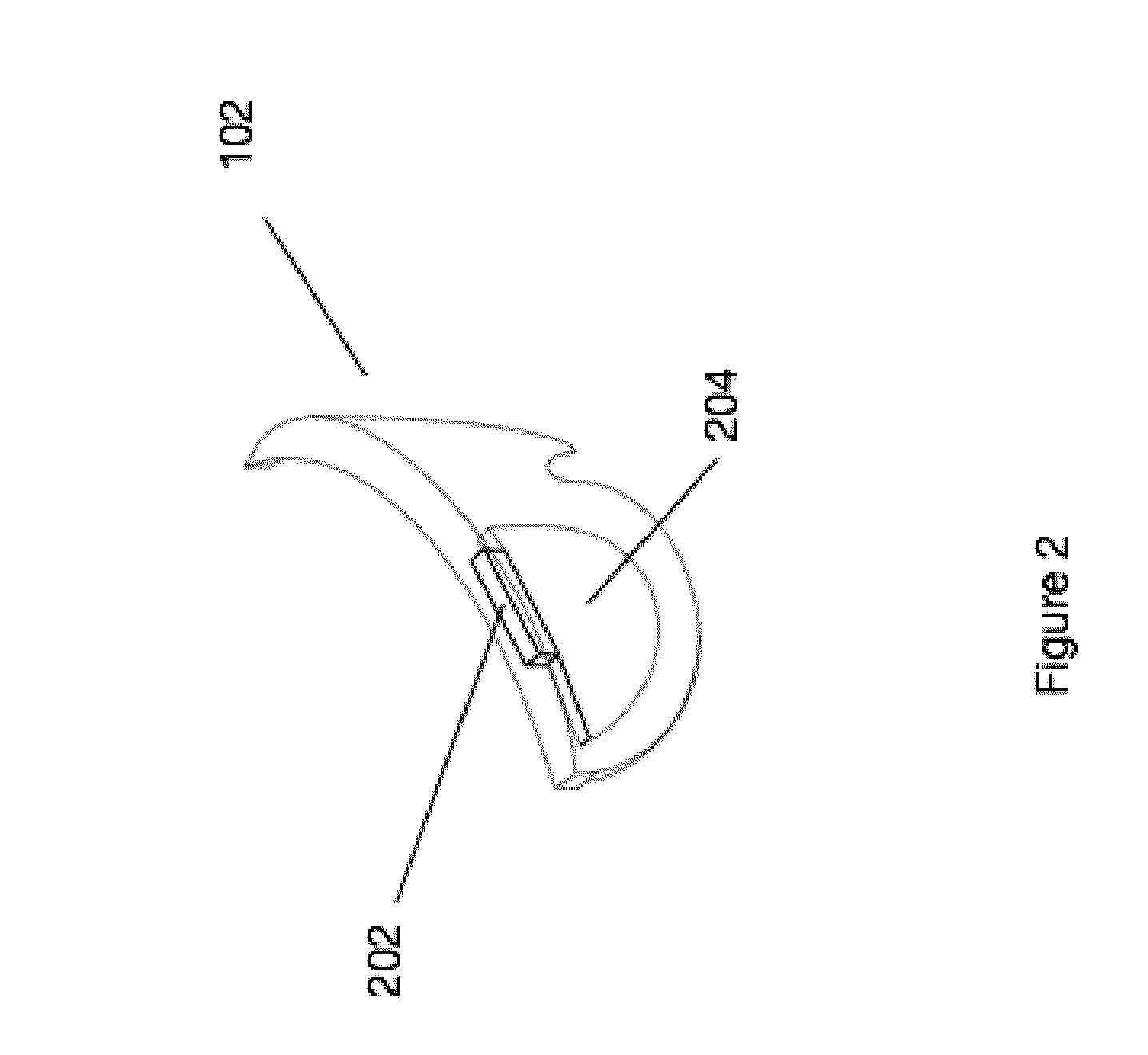
Aspects of the present disclosure relate to mounting electronics and optical systems in head-worn see-through computer displays. In embodiments, a head worn computer includes an optical chassis with a rigid open box structure configured to provide a stable optical mounting reference plane and a plurality of image source reference planes. The head worn computer further includes a first image source mounted on one of the image source reference planes to project first image light through a first hole in the optical mounting reference plane and a second image source mounted on a second of the image source reference planes and configured to project second image light through a second hole in the optical mounting reference plane. An outer frame holds the optical chassis such that, when worn by a user, the first and second image light is aligned with the eyes of the user.

Description

CLAIM TO PRIORITY[0001]This application is a continuation-in-part of U.S. non-provisional application Ser. No. 14 / 589,713 (ODGP-4006-U01), filed Jan. 5, 2015.[0002]U.S. non-provisional application Ser. No. 14 / 589,713 (ODGP-4006-U01) is a continuation-in-part of U.S. non-provisional application Ser. No. 14 / 559,126 (ODGP-4005-U01), filed Dec. 3, 2014.[0003]All of the above applications are incorporated herein by reference in their entirety.BACKGROUND[0004]1. Field of the Invention[0005]This invention relates to see-through computer display systems.[0006]2. Description of Related Art[0007]Head mounted displays (HMD) and particularly HMDs that provide a see-through view of the environment are sensitive to the effects of stray light. Where, stray light includes light that is not intended to be included in the displayed image, including light that is scattered or inadvertently reflected from surfaces within the optics of the HMD. This stray light reduces the sharpness and contrast of the ...

Claims


Application Information

Patent Timeline
Patent Type & Authority Applications(United States)
IPC IPC(8): G02B27/01
CPCG02B27/0172G02B27/0093G02B2027/012G02B2027/0169G02B2027/014G02B26/0833G02B27/1033G02B27/283G06F1/163G06F3/005G06F3/013G06F3/017G06T19/006G02B2027/0194G02B2027/0178G02B2027/0118G02B2027/0138G02B2027/0187G02B27/0176G02B27/017G02B2027/0174G06F3/011G06F3/0304
Inventor BORDER, JOHN N.YAMAMOTO KOHATSU, KEI EDGARDOELKATCHA, KARIMHADDICK, JOHN D.OSTERHOUT, RALPH F.
Owner OSTERHOUT GROUP INC
Learn More