Flat tube evaporator with enhanced refrigerant flow passages

a technology of evaporator and refrigerant flow, which is applied in the field of flat tube evaporator with enhanced ref, evaporator, can solve the problems of difficult fin bonding to the surface, difficult fabrication, and tubes that can be subjected to relatively low refrigerant side pressure, etc., and achieves enhanced quasi-pool boiling, increased heat transfer rate through the tube, and enhanced nucleate boiling

Active Publication Date: 2006-07-25
MAHLE INT GMBH
View PDF13 Cites 26 Cited by
  • Summary
  • Abstract
  • Description
  • Claims
  • Application Information

AI Technical Summary

Benefits of technology

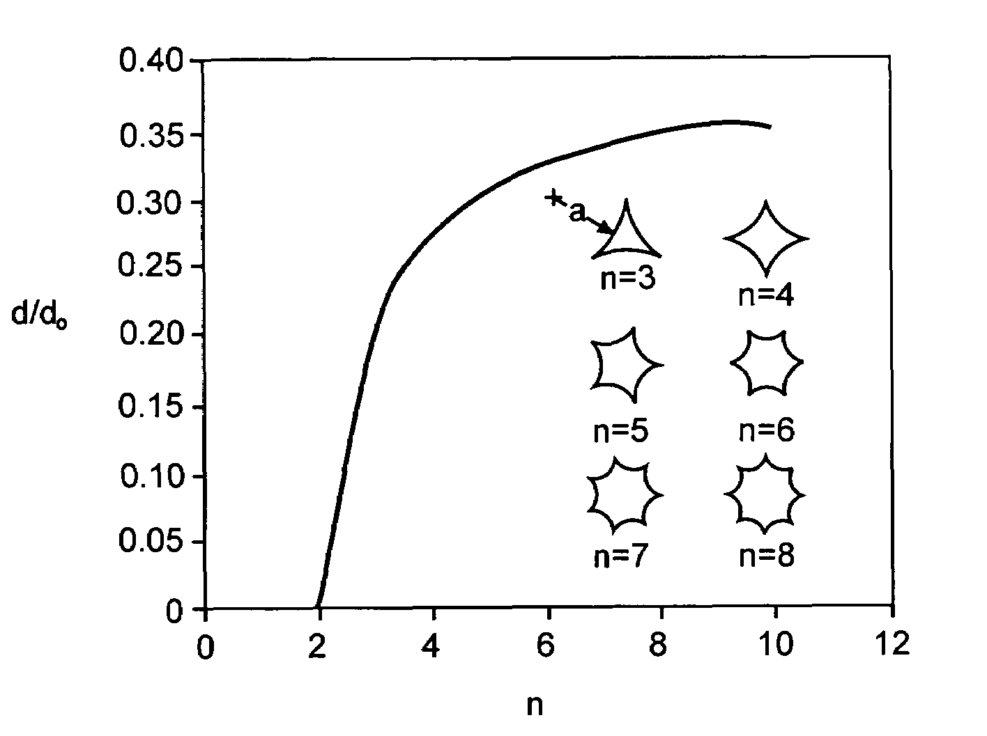
[0008]Accordingly, the subject invention overcomes the limitations of the related art by providing a heat exchanger of the type in which a cross-flow of a fluid is directed in an upstream to downstream direction on the external surface of the heat exchanger to induce a transfer of thermal energy between the external fluid and a refrigerant circulating within the heat exchanger. The heat exchanger includes a pair of spaced tanks. A plurality of heat exchange tubes extends between the tanks in fluid communication therewith. At least one of the tubes includes a plurality of flow passages whose interior sidewalls define at least one corner having an included angle of less than ninety degrees to promote intense quasi pool boiling. Reducing the included angle of the corner increases the volume of the liquid refrigerant drawn into the corner by surface tension. This not only enhances nucleate boiling, but also creates secondary flow patterns normal to the primary flow of the refrigerant along the longitudinal axis of the passage defined by the interior sidewalls. An increase in the secondary flow causes a corresponding increase in turbulence within the passage, which further enhances quasi pool boiling and increases the rate of heat transfer through the tube.

Problems solved by technology

For example, the embossed patterns on the surfaces of the plates make it difficult for the fins to bond to the surfaces.
Furthermore, the plates are expensive to fabricate and result in tubes that can be subjected to relatively low refrigerant side pressure.
However, none of these patents deal with the optimal dimensions of the circular or noncircular refrigerant flow passages within the extruded flat tubes nor do they deal with the optimal number of tubes in each pass of a multi-pass evaporator.
However, the prior art tubes are not designed to ensure that such boiling optimizes the amount of heat transferred through the tube.

Method used


Image

  • Flat tube evaporator with enhanced refrigerant flow passages
  • Flat tube evaporator with enhanced refrigerant flow passages
  • Flat tube evaporator with enhanced refrigerant flow passages

Examples


Embodiment Construction

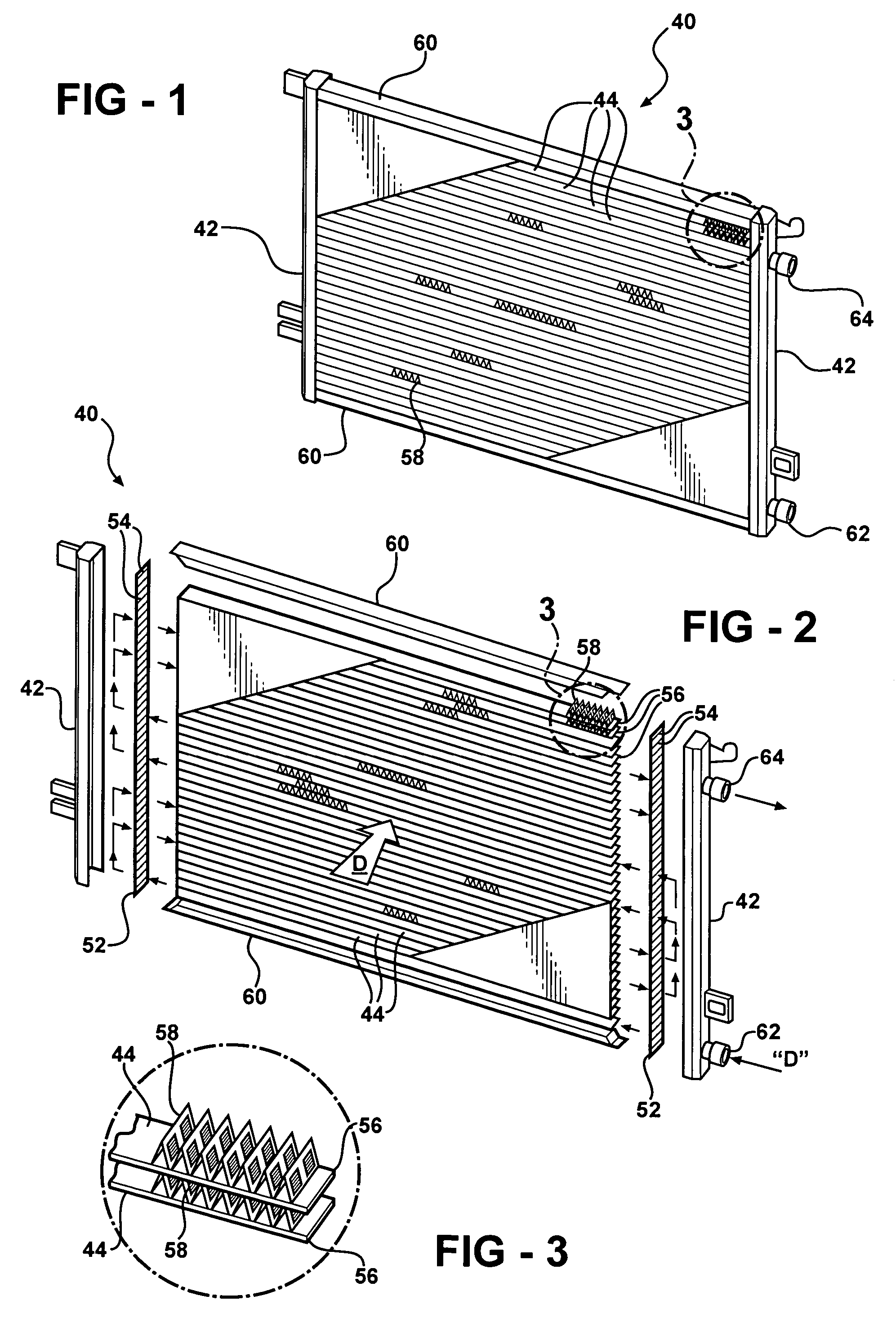
[0045]Referring to the Figures, wherein like numerals indicate like or corresponding parts throughout the several views, a heat exchanger is generally shown at 40 in FIGS. 1 and 2. The heat exchanger 40 is an evaporator of the type wherein an upstream to downstream fluid flow, such as airflow indicated by the arrow “D”, is directed over its external surface, which induces a transfer of thermal energy between the external fluid flow and a refrigerant circulating through interior of the heat exchanger 40.

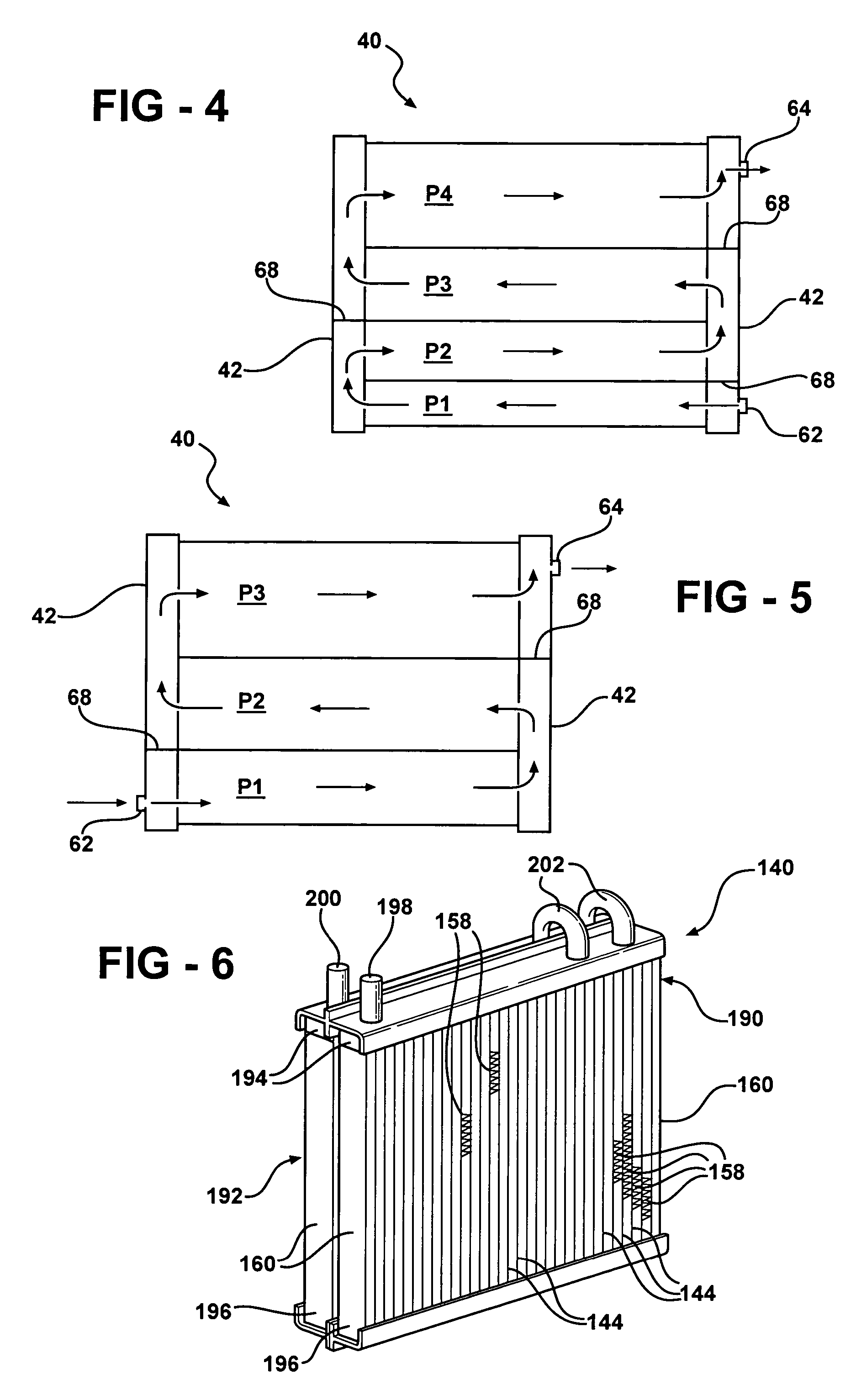
[0046]The heat exchanger 40 has an unfolded core design and includes a pair of spaced tanks 42 comprising a plurality of flow separators 68, shown clearly in FIGS. 4 and 5, to divide the incoming refrigerant flow into a number of flow passes (vide infra). A plurality of heat exchange tubes 44, divided into groups of tubes to correspond to various flow passes, extends between the tanks 42 in fluid communication therewith. As described in greater detail with reference to FIGS. 8 and 9 b...


PUM


Abstract

A heat exchanger for a heating, ventilating and air conditioning system comprises a plurality of heat exchange tubes extending between a pair of spaced header tanks and arranged in groups of tubes with varying number of tubes in each group to cause a refrigerant to flow in multiple passes in the interior of the tubes across another fluid flowing on the exterior of the tubes. The heat exchange tubes comprise a plurality of flow passages having at least one corner formed by a pair of straight or arcuate sides with an included angle of less than or equal to ninety degrees, more preferably less than or equal to thirty degrees, to promote intense pool boiling within the flow passages. In addition to at least one corner region, the flow passage has a passage-specific optimal hydraulic diameter determined by the relationship between the optimal hydraulic diameter of the passage and the optimal hydraulic diameter of a baseline circular passage.

Description

BACKGROUND OF THE INVENTION[0001]1. Field of the Invention[0002]The subject invention relates to heat exchangers, and more specifically to an evaporator, that utilizes flat tubes having a plurality of flow passages extending therethrough.[0003]2. Description of the Related Art[0004]Evaporators for automobile heating, ventilation and air conditioning (HVAC) systems are well known in the art as described in the U.S. Pat. Nos. 4,470,455 and 4,535,839. Such evaporators typically include a core formed by a plurality of tubes between which fins are disposed for permitting ambient air to flow across the exterior of the tubes. The tubes are in fluid communication with spaced tanks to allow refrigerant—working fluid of the system capable of undergoing transformation from liquid to vapor and vice versa—to flow from one tank to the other through the tubes. This permits heat exchange between the refrigerant and the ambient air as the refrigerant flows through the tubes.[0005]Various evaporator ...

Claims


Application Information

Patent Timeline
Patent Type & Authority Patents(United States)
IPC IPC(8): F28F1/42F28D1/053F28F1/02
CPCF28D1/05391F28F1/022F28D2021/0071
Inventor BHATTI, MOHINDER SINGHJOSHI, SHRIKANT MUKUNDMEHENDALE, SUNIL S.
Owner MAHLE INT GMBH
Why Eureka
Try Eureka