Optical switch device

Inactive Publication Date: 2006-11-02
ORMON CORP
View PDF3 Cites 0 Cited by
  • Summary
  • Abstract
  • Description
  • Claims
  • Application Information

AI Technical Summary

Benefits of technology

[0014] In the optical switch device of the present invention, the clamping coil and clamping magnet are not required to be stacked in the height direction of the device because a clamping magnetic drive circuit is used that is provided with a clamping coil and a clamping magnet that generates magnetic flux which interlinks with the

Problems solved by technology

Optical waveguide switching devices of the optical waveguide type have a considerable optical loss due to coupling and branching of the optical waveguide fiber.
The lifespan of the device is relatively short since power must be constantly fed to the heater in order to maintain the switched condition of the optical waveguide.
MEMS-type optical switches suffer from high manufacturing costs because semiconductor processes are used.
However, an optical switching device of the type that moves the rectangular prism mirror to switch the coupled state

Method used


Image

  • Optical switch device
  • Optical switch device
  • Optical switch device

Examples


Embodiment Construction

[0015] An optical switch device in which the present invention has been applied is described below with reference to the drawings.

(Basic Principles of the Optical Switch Device)

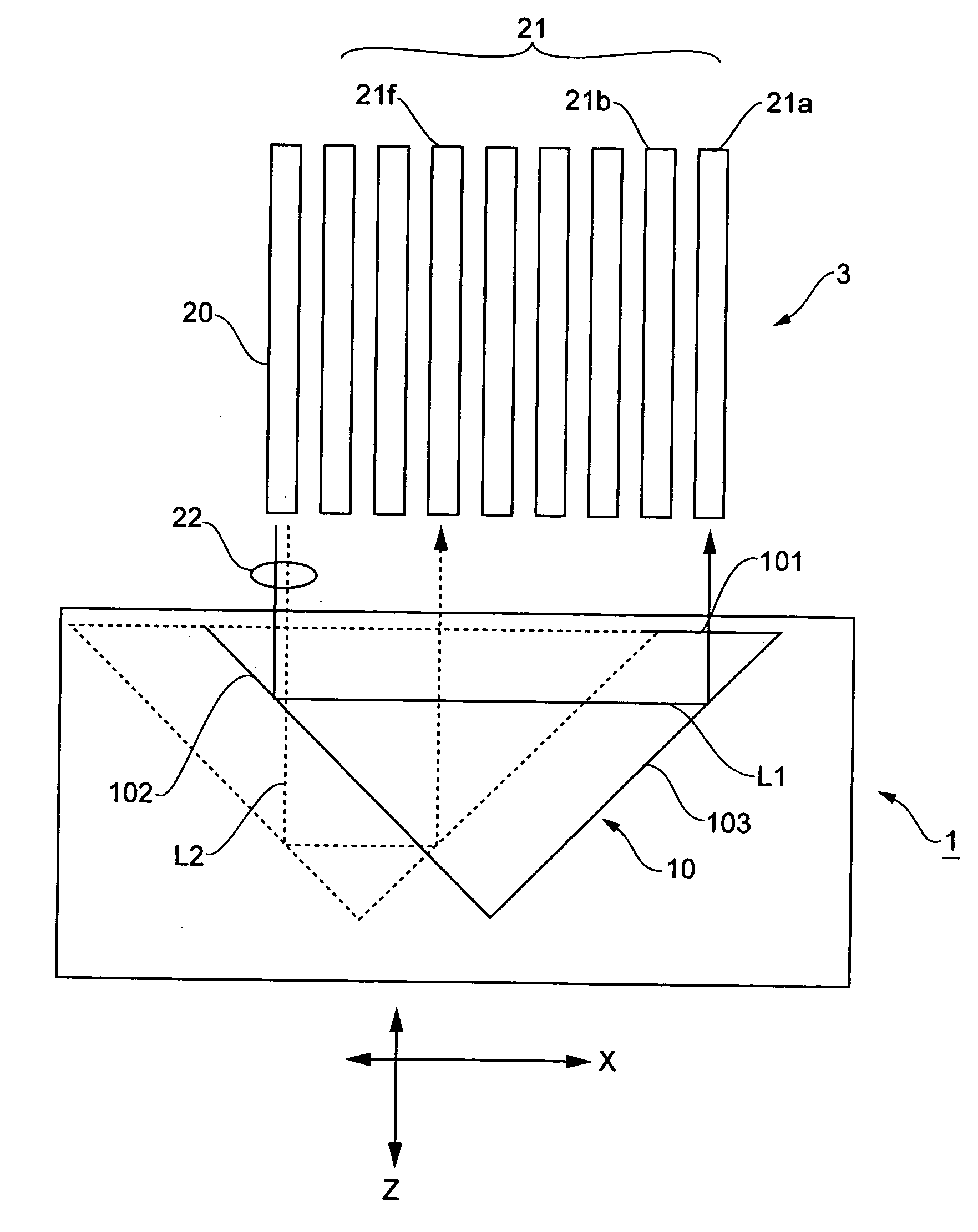
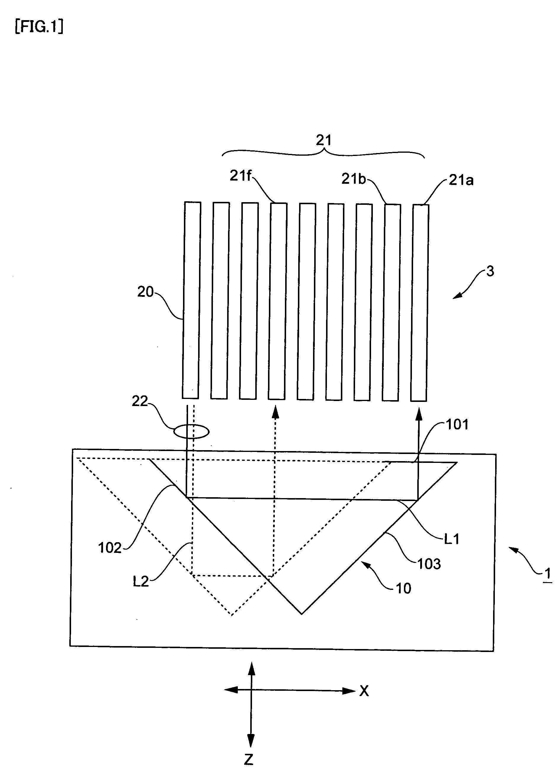
[0016]FIG. 1 is a diagram schematically depicting the basic principles of the optical switch device of the present invention. In the following description, the mutually perpendicular directions will be described as the X-, Y-, and Z-directions.

[0017] In FIG. 1, the optical switch device 1 is an 8-channel optical switch device in which a single input-side optical fiber 20 extending in the Z-direction and eight output-side optical fibers 21 are disposed in parallel along the X-direction, and light output from the input-side optical fiber 20 can be directed to the any of the eight output-side optical fibers 21. The optical fiber array 3 composed of the input-side optical fiber 20 and output-side optical fibers 21 is configured so that the optical fibers are arranged in the X-direction at equal intervals at a...


PUM


Abstract

An optical switch device (1) of such a type that the coupled state of light guides is switched by moving a light reflective member capable of securely preventing a movable body with the light reflective member from being displaced and allowing a reduction in thickness, comprising a pressing member (41) switching the movable body (2) with a prism mirror (10) mounted thereon between a clamped state and an unclamped state, a twisted spring (60) energizing the pressing member in a clamping direction, and a magnetic drive circuit (45) for clamping driving the pressing member (41) in the unclamped state against the torsion spring (60). The magnetic drive circuit (45) for clamping further comprises a clamp coil (72) on the fixed member (13) side and clamp magnets (70, 71) on the pressing member (41) side. The clamp magnets (70, 71) are disposed so as to hold the clamp coil (72) from the inside and outside of the opening thereof with the different poles thereof opposed to each other.

Description

TECHNICAL FIELD [0001] The present invention relates to an optical switch device that is used as an optical waveguide switching device for fiber-optic exchangers, or as a variable optical attenuator for suitably attenuating optical input, and more specifically relates to a technique for clamping a movable member mounted with a light-reflecting member that switches the light-emitting position. BACKGROUND ART [0002] Known as an optical switch device that switches the coupled state of optical fibers and other optical waveguides is MEMS (Micro Electro Mechanical System), which uses a micro actuator and a micro optical element produced by a semiconductor process (JP-A 2002-250874, for example). [0003] Optical waveguide switching devices of the optical waveguide type have a considerable optical loss due to coupling and branching of the optical waveguide fiber. The lifespan of the device is relatively short since power must be constantly fed to the heater in order to maintain the switched ...

Claims


Application Information

Patent Timeline
IPC IPC(8): G02B6/26G02B26/08G02B6/35
CPCG02B6/3516G02B6/352G02B6/358G02B6/3572G02B6/3548
Inventor FUJISAWA, EIJITSURUTA, TOSHIFUMAKAWAMOTO, RYUJINAKANISHI, YOICHISUZUKI, YUICHI
Owner ORMON CORP
Why Eureka
Try Eureka