Image display system and head-mounted display device

a display system and display device technology, applied in the field of image display system and head-mounted display device, can solve the problems of not so much difference in case, less space between operation windows, and difficulty in operation, and achieve the effect of extending the observation range of the whole imag

Active Publication Date: 2014-09-11
SEIKO EPSON CORP
View PDF20 Cites 13 Cited by
  • Summary
  • Abstract
  • Description
  • Claims
  • Application Information

AI Technical Summary

Benefits of technology

[0010]An advantage of some aspects of the invention is to provide an image display system and a head-mounted display device that may enlarge an observation range of an image.
[0016]According to the first aspect, the visual direction acquisition unit shows the current visual direction as the angle with respect to the reference visual direction with the direction toward the first display device displaying the first image as the reference visual direction. Here, the area extracted as the first image in the whole image is an area to which the reference visual direction is directed from the reference point corresponding to the position of the user, and the area acquired as the second image in the whole image may be easily set by the current visual direction represented by the angle with respect to the reference visual direction. Therefore, the extraction of the second image by the extraction unit may be easily and reliably performed.
[0018]According to the first aspect, the amount of displacement of the visual direction from the state in which the visual direction of the user coincides with the reference visual direction is acquired from the detection result by the displacement detection unit, and thereby, the visual direction acquisition unit may easily acquire the current visual direction of the user. Therefore, the visual direction acquisition processing may be simply performed.
[0024]Further, if the current visual direction is not the direction toward the first display device, the drive control unit sets the shutter to the shield state. Thereby, the visual recognition of the outside world by the user may be reduced and the second image displayed in the display unit may be clearly observed. Therefore, the higher sense of immersion may be obtained.
[0030]According to the second aspect, not only the image of the area preset in the whole image but also the image of the area in response to the visual direction of the user in the whole image may be observed. Therefore, the observation range of the whole image may be enlarged and the whole image in the larger size may be observed without reduction.

Problems solved by technology

However, in the configuration, there has been a problem that, when the number of users becomes larger, the respective operation windows become smaller and the operation becomes harder.
However, there has been a problem that the case is not so much different from the case where the respective users individually play a video game.
Here, when the size of the first image and the size of the second image seen by the user are different, the sense of the first image and the second image as images respectively forming partial images of the whole image is hard to be obtained.

Method used


Image

  • Image display system and head-mounted display device
  • Image display system and head-mounted display device
  • Image display system and head-mounted display device

Examples


first embodiment

[0040]As below, the first embodiment of the invention will be explained with reference to the drawings.

Overall Configuration of Image Display System

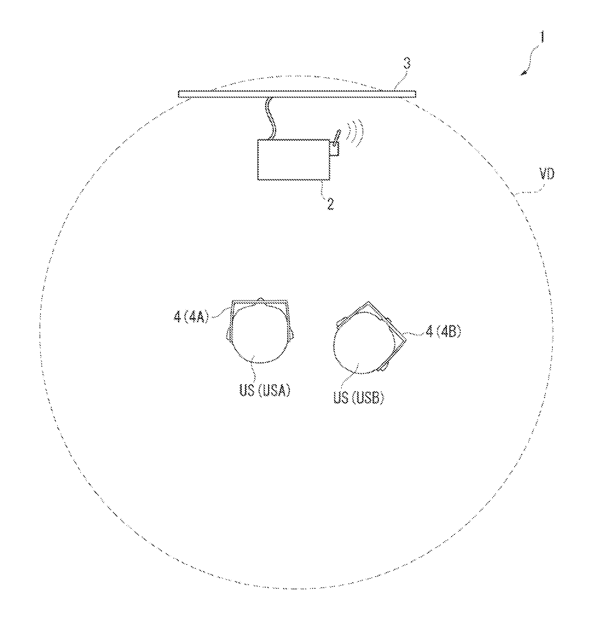
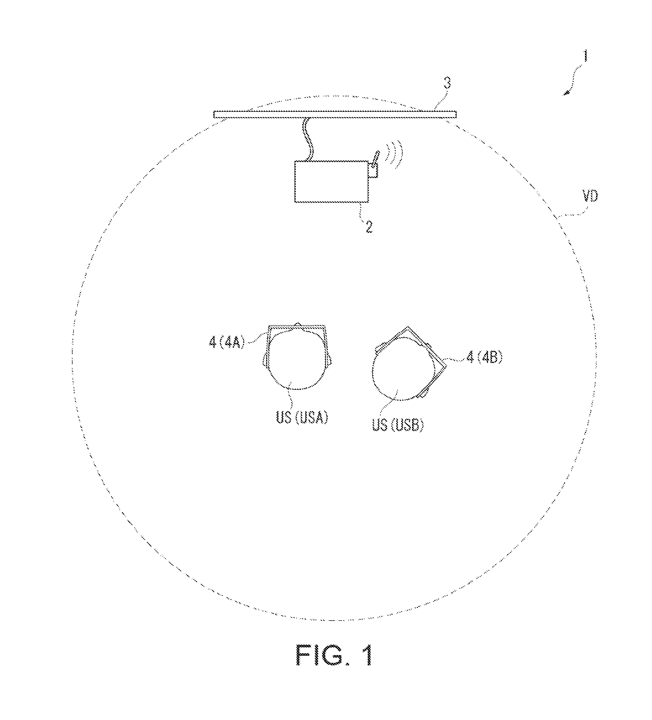
[0041]FIG. 1 is a schematic diagram showing an overall configuration of an image display system 1 according to the embodiment.

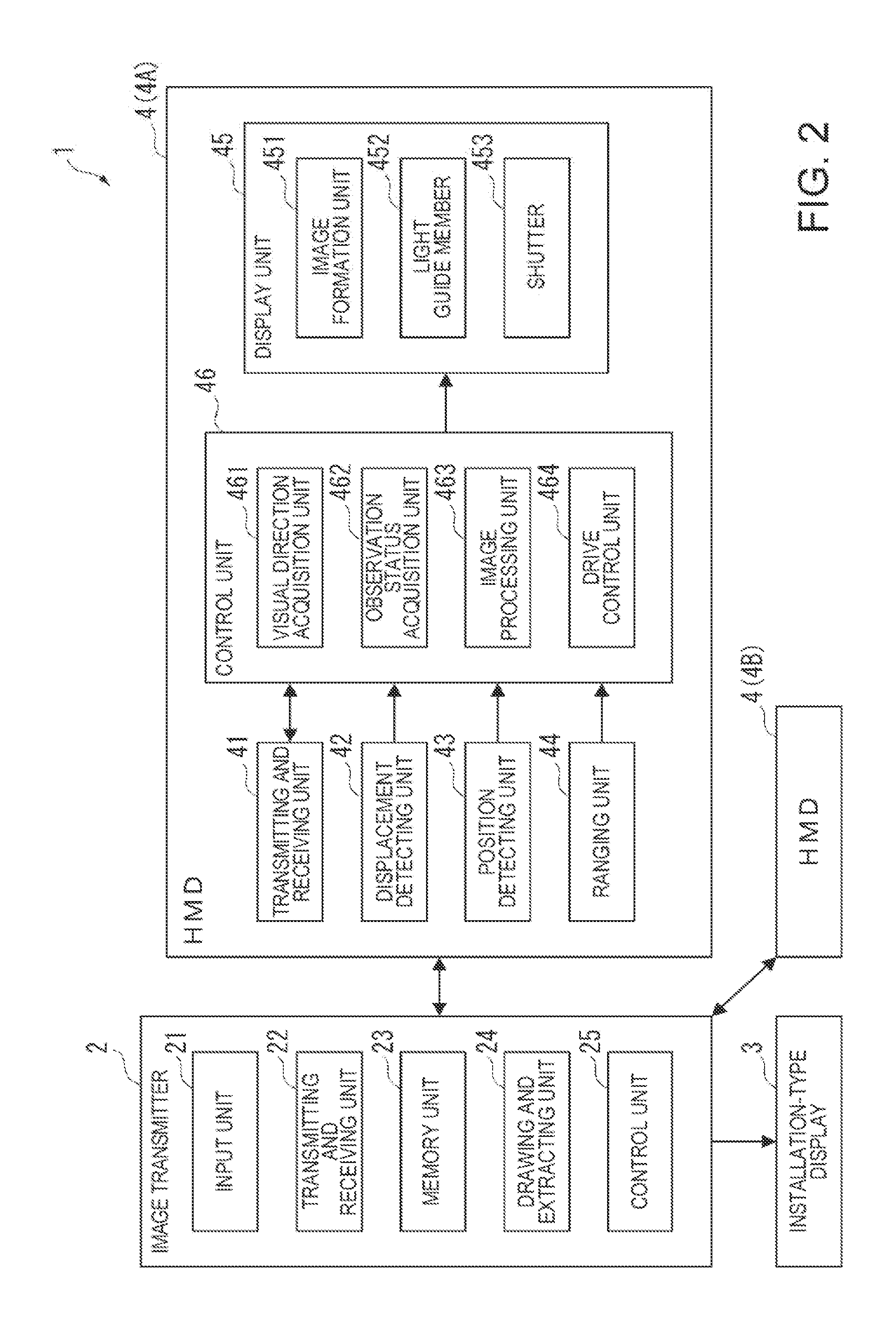
[0042]As shown in FIG. 1, the image display system 1 according to the embodiment includes an image transmitter 2, and an installation-type display (hereinafter, may be abbreviated to “display”) 3 and a head-mounted display (hereinafter, may be abbreviated to “HMD”) 4 (4A, 4B) that are connected to the image transmitter 2. The display 3 and the HMD 4 (4A, 4B) respectively display images in response to image information (including image data and image signals) transmitted from the image transmitter 2. One of the features of the image display system 1 is in setting a virtual display surface VD having a circular shape around a current position of a user US (USA, USB) in a plan view with respect to each user US, fittin...

second embodiment

[0124]As below, the second embodiment of the invention will be explained. Note that, in the following explanation, the same or substantially the same parts as the parts that have been already explained have the same signs and their explanation will be omitted.

[0125]FIG. 7 is a block diagram showing a configuration of an HMD 5 according to the embodiment.

[0126]The HMD 5 according to the embodiment is a head-mounted display device having a part of the function of the above-described image transmitter 2 to draw a whole image and display an image within an area corresponding to the current visual direction of the user in the whole image. The HMD 5 includes a see-through head-mounted display like the HMD 4 and has a transmitting and receiving unit 41, a displacement detecting unit 42, a display unit 45, and a frame (not shown), and further has an input unit 47, a memory unit 48, and a control unit 46A as shown in FIG. 7.

[0127]The input unit 47 has a plurality of entry keys and outputs op...


PUM


Abstract

An image display system includes an image transmitter, a first display device that displays a first image, and a second display device that displays a second image, the second display device includes a display device side receiving unit that receives the second image, a display unit that displays the second image, a visual direction acquiring unit that acquires a current visual direction of the user, and a display device side transmitting unit that transmits the current visual direction, and the image transmitter includes a transmitter side receiving unit that receives the current visual direction, an extracting unit that extracts the first image as an image of a partial area in a whole image and the second image as an image of an area in response to the current visual direction in the whole image, and a transmitter side transmitting unit that transmits the first and second images.

Description

BACKGROUND[0001]1. Technical Field[0002]The present invention relates to an image display system and a head-mounted display device.[0003]2. Related Art[0004]In related art, as image display devices for displaying images, head-mounted display devices (head-mounted displays) worn on heads of users have been known in addition to displays installed in predetermined positions (for example, see Patent Document 1 (JP-A-2012-163639)).[0005]A head-mounted display disclosed in Patent Document 1 is adapted to be a see-through head-mounted display that enables observation of the outside world. Further, the head-mounted display modulates light output from a backlight provided in a temple of a frame in response to image information using a liquid crystal display device, and guides the light to an eye of a user via a lens using a light guide plate. Thereby, an image is visually recognized.[0006]In a video game executed by a PC (Personal Computer), a game machine, or the like and played by operatio...

Claims


Application Information

Patent Timeline
Patent Type & Authority Applications(United States)
IPC IPC(8): A63F13/219
CPCA63F13/04A63F2300/203A63F2300/301A63F2300/308A63F13/352A63F13/26A63F2300/303A63F13/98A63F13/25A63F13/52
Inventor KOBAYASHI, SHINICHITSUDA, ATSUNARI
Owner SEIKO EPSON CORP
Why Eureka
Try Eureka