Support structure, robot and parallel link robot

a support structure and robot technology, applied in the direction of manipulators, manufacturing tools, program-controlled manipulators, etc., can solve the problems of easy liquid retention in the gap, difficult cleaning of the gap, etc., and achieve the effect of easy and reliable cleaning and drying

Active Publication Date: 2021-07-01
FANUC LTD
View PDF3 Cites 0 Cited by
  • Summary
  • Abstract
  • Description
  • Claims
  • Application Information

AI Technical Summary

Benefits of technology

[0009]According to an aspect, cleaning and drying can be easily and reliably performed, and a structure can be used hygienically.

Problems solved by technology

If the space is made between the clamp component and the link member, disadvantages occur that the gap is difficult to clean and liquid of cleaning fluid easily remains in the gap.

Method used


Image

  • Support structure, robot and parallel link robot
  • Support structure, robot and parallel link robot
  • Support structure, robot and parallel link robot

Examples


embodiment

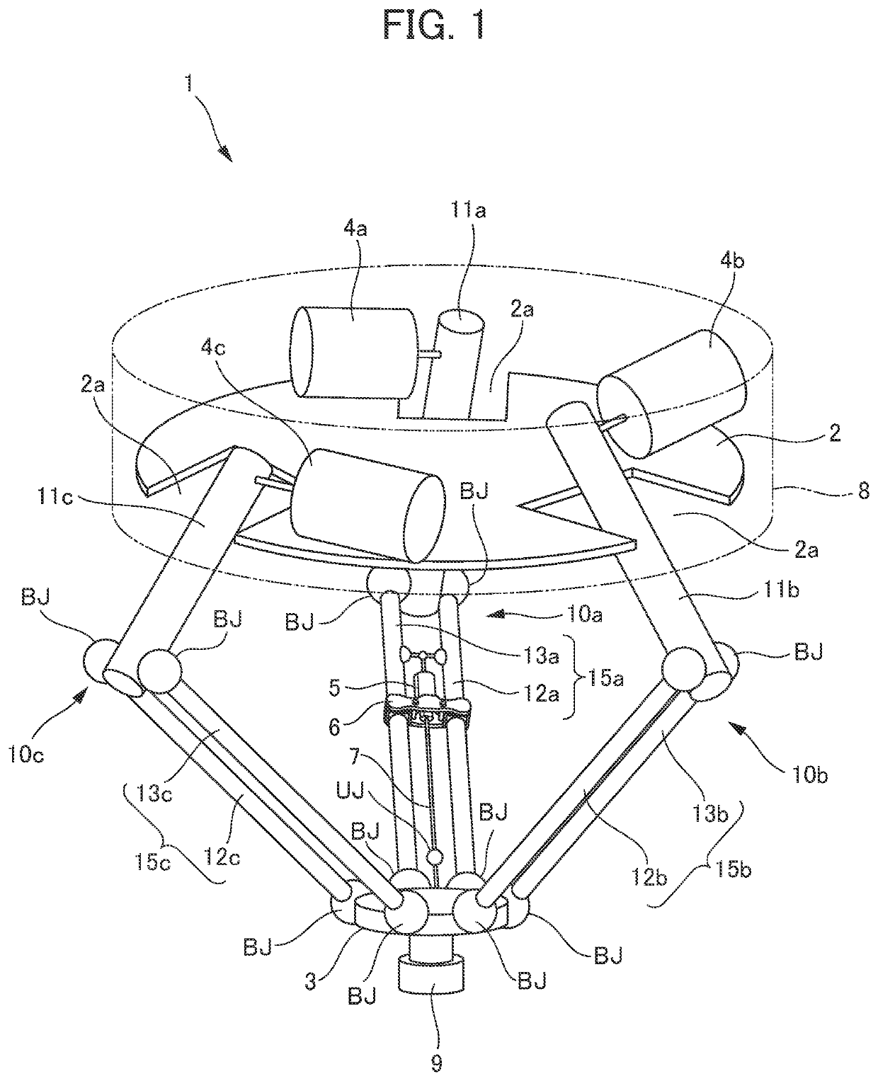
[0024]Hereinafter, description will be made as to an embodiment of the present disclosure with reference to the drawings. FIG. 1 shows a parallel link robot 1 comprising a support structure according to the embodiment of the present disclosure. As shown in FIG. 1, the parallel link robot 1 comprises a base 2 housed in a housing 8, a movable part 3 having a disk shape, three arms 10a to 10c coupling the base 2 and the movable part 3 in parallel, three actuators 4a to 4c arranged on the base 2 to drive the respective arms 10a to 10c, a mounting part 9 mounted to the movable part 3, an actuator for a wrist 5, a drive shaft 7 that transmits a driving force of the actuator for the wrist 5 to the mounting part 9, a fixing part 6 that fixes the actuator for the wrist 5 to the arm 10a, and a universal joint UJ provided in a middle of the drive shaft 7.

[0025]Note that in the following description, description about an upward-downward direction is based on arrangement of FIG. 1. Furthermore, ...

modification example

[0061]Next, modification examples will be described in which a part of the above embodiment is modified. In the following description, the same components as in the above embodiment are denoted with the same reference numerals, description thereof is omitted, and differences will be mainly described.

[0062]FIGS. 8A and 8B show a modification example of the elastic member 90. As shown in FIG. 8A, the elastic member 30 is provided with one cut 90d extending from an inner circumferential surface 90b of a hole 90a, in which a link member 12a, 13a is to be disposed, to one side surface 90c. The elastic member 90 includes a pair of dividing surfaces 91b that face each other via the cut 90d, as shown in FIG. 8B. As shown in FIG. 8B, the elastic member 90 is elastically deformed to separate the dividing surfaces 91b, so that the link member 12a, 13a can be passed between the separated dividing surfaces 91b. Consequently, the elastic member 90 can be removably mounted to the link member 12a, ...


PUM


Abstract

Provided is a support structure comprising a link member (a rod-like member), a clamp member disposed to surround the link member, and an elastic member disposed between the link member and the clamp member, the support structure supports the link member inside the clamp member via the elastic member, and the elastic member comprises a liquid impermeable material, and fills a space between the link member and the clamp member.

Description

[0001]This application is based on and claims the benefit of priority from Japanese Patent Application No. 2019-236379, filed on Dec. 26, 2019, the content of which is incorporated herein by reference.BACKGROUND OF THE INVENTIONField of the Invention[0002]The present invention relates to a support structure that supports a rod-like member, a robot comprising the support structure, and a parallel link robot comprising the support structure.Related Art[0003]In recent years, in various industrial fields, a parallel link robot has been used as a robot, suitable for moving and handling a task object in a three-dimensional space. The parallel link robot comprises a parallel link mechanism including a plurality of arms arranged in parallel with one another to support a movable part disposed at a lower end, and the respective arms are driven and controlled by an actuator, to dispose the movable part at an arbitrary position in the three-dimensional space.[0004]As a parallel link robot, ther...

Claims


Application Information

Patent Timeline
Patent Type & Authority Applications(United States)
IPC IPC(8): B25J9/10B25J17/00B25J9/16B25J9/00
CPCB25J9/106B25J9/0021B25J9/1623B25J17/00B25J9/0054B25J9/0051
Inventor OGAWA, REISHIN
Owner FANUC LTD
Why Eureka
Try Eureka