Methods and systems for control of microfluidic devices

a microfluidic device and control system technology, applied in the field of microfluidics, can solve the problems of difficult generation and lack of well-structured control systems for such micro-droplet-based microfluidic devices

Inactive Publication Date: 2006-03-07
HANDYLAB
View PDF110 Cites 271 Cited by
  • Summary
  • Abstract
  • Description
  • Claims
  • Application Information

AI Technical Summary

Benefits of technology

[0009]Thus, the present invention has for one of its several objects the provision of programmable control systems and software for what are known herein as “digital” microfluidic devices. The control systems provided, reflecting the design of preferred microfluidic devices themselves, have a generally hierarchical design in which detailed and lower-level device control is organized into a smaller number of basic control functions, while overall and higher-level device control is organized as sequences of the basic function that cause a particular device to carry out intended reactions of analyses. The control systems of the present invention are thereby adaptable to many different types of digital microfluidic devices and intended reactions; they are scalable to devices of various complexities, simple to program and economical.

Problems solved by technology

These devices are relatively disadvantageous because, inter alia, they require larger volumes of reactants by virtue of their flow-based design, and fluid control by electro-osmotic and electrophoretic forces typically requires relatively large voltages, which may be dangerous and are difficult to generate in small portable control devices.
However, to the knowledge of the inventors, no well-structured control systems have been provided for such micro-droplet-based microfluidic devices that exploits the essential advantages of such devices.

Method used


Image

  • Methods and systems for control of microfluidic devices
  • Methods and systems for control of microfluidic devices
  • Methods and systems for control of microfluidic devices

Examples


Embodiment Construction

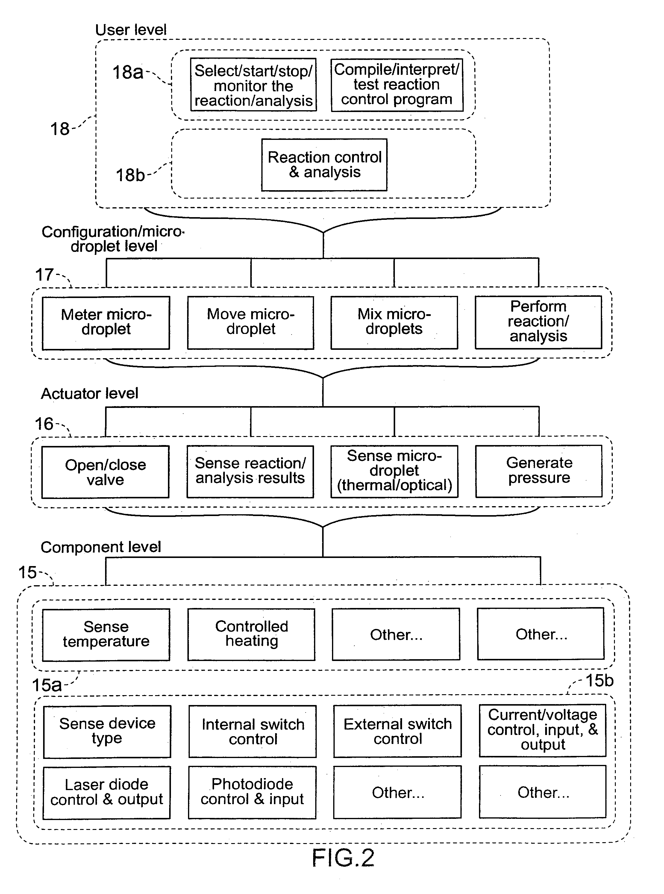
[0044]Section 5.1 generally describes preferred microfluidic devices controlled by the systems and methods of the present invention; section 5.2 describes preferred embodiments of these control systems and methods in view of the characteristics of preferred microfluidic devices; section 5.3 describes more preferred thermally-controlled microfluidic devices and their more preferred control systems and methods; furthermore, section 5.3 describes additional embodiments.

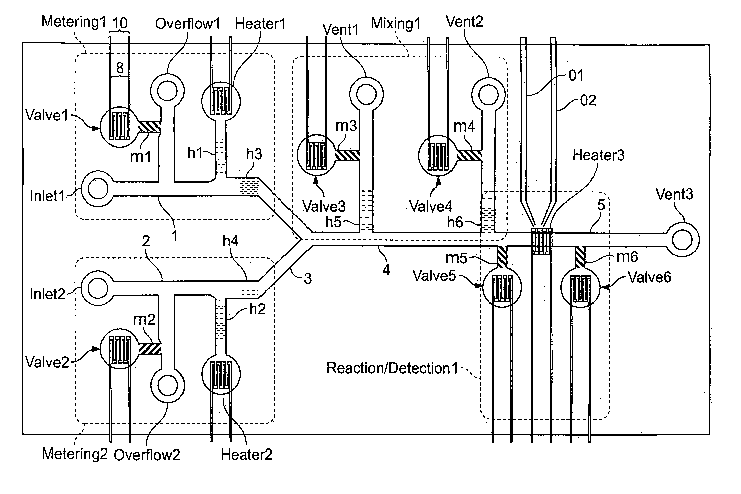
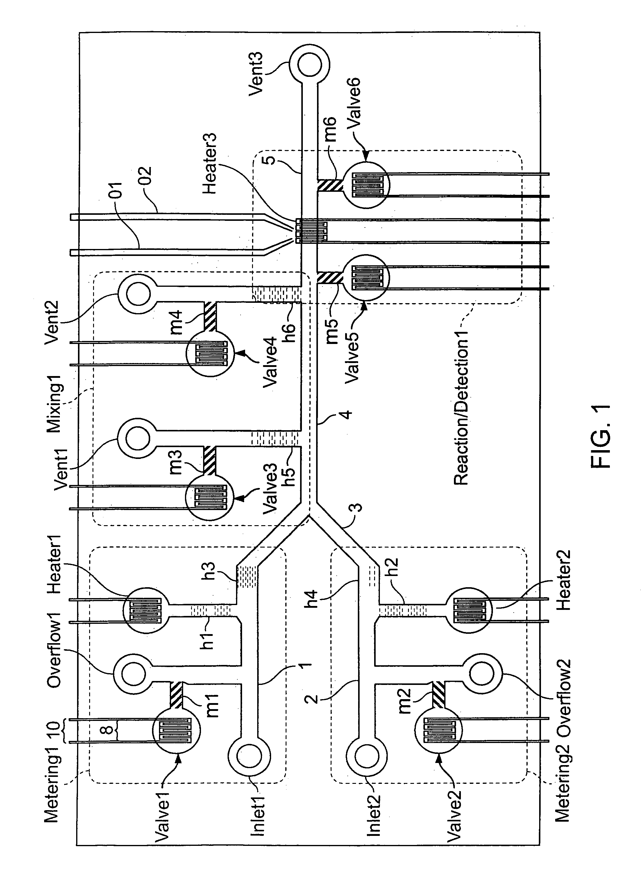
5.1. Preferred Microfluidic Devices

[0045]The systems and methods of the present invention control microfluidic devices that operate in a manner referred to herein as “digital”. In this sub-section, the general characteristics of “digital” microfluidic devices are first described. Subsequently, a more preferred type of thermally-controlled “digital” microfluidic device is described.

5.1.1. Digital Micro-Fluidic Devices

[0046]Microfluidic devices perform chemical or biochemical reactions or analyses by manipulating fluid rea...


PUM

PropertyMeasurementUnit
lengthsaaaaaaaaaa
volumesaaaaaaaaaa
volumesaaaaaaaaaa

Abstract

The present invention provides control methods, control systems, and control software for microfluidic devices that operate by moving discrete micro-droplets through a sequence of determined configurations. Such microfluidic devices are preferably constructed in a hierarchical and modular fashion which is reflected in the preferred structure of the provided methods and systems. In particular, the methods are structured into low-level device component control functions, middle-level actuator control functions, and high-level micro-droplet control functions. Advantageously, a microfluidic device may thereby be instructed to perform an intended reaction or analysis by invoking micro-droplet control function that perform intuitive tasks like measuring, mixing, heating, and so forth. The systems are preferably programmable and capable of accommodating microfluidic devices controlled by low voltages and constructed in standardized configurations. Advantageously, a single control system can thereby control numerous different reactions in numerous different microfluidic devices simply by loading different easily understood micro-droplet programs.

Description

1. FIELD OF THE INVENTION[0001]The present invention relates to the field of microfluidics. More particularly, the present invention is directed to control methods, control systems, and control software for microfluidic devices that operate by moving discrete micro-droplets through a sequence of determined configurations.2. BACKGROUND OF THE INVENTION[0002]Micro / nano technology devices are known in the art as devices with components on the scale of 1 μm to 100s of μm that cooperate to perform various desired functions. In particular, microfluidic devices are micro / nano technology devices that perform fluid handling functions, which, for example, cooperate to carry out a chemical or biochemical reaction or analysis.[0003]Most microfluidic devices in the prior art are based on fluid flowing through microscale passages and chambers, either continuously or in relatively large aliquots. Fluid flow is usually initiated and controlled by electro-osmotic and electrophoretic forces. See, e.g...

Claims


Application Information

Patent Timeline
Patent Type & Authority Patents(United States)
IPC IPC(8): G01N31/00G01N1/00G01N1/10G01N27/26G01N27/27B01F13/00B01J19/00B01L3/00B01L7/00B81B1/00G01N1/28G01N37/00
CPCB01F13/0071B01J19/0093B01L3/502792B01L7/52G01N1/4077G01N35/1083B01L3/502784B01F13/0079Y10T436/12B01J2219/00783B01J2219/00828B01J2219/00831B01J2219/00833B01J2219/00835B01J2219/00837B01J2219/0086B01J2219/00862B01J2219/00873B01J2219/00889B01J2219/00891B01J2219/00936B01J2219/00943B01J2219/00945B01J2219/00961B01J2219/0097B01J2219/00986B01L2200/0605B01L2200/0673B01L2300/0816B01L2400/0442B01L2400/0677B01L2200/14B01L2400/0493Y10T436/2575Y10T436/25B01F33/3021B01F33/3033
Inventor HANDIQUE, KALYANGANESAN, KARTHIKBRAHMASANDRA, SUNDARESH N
Owner HANDYLAB
Why Eureka
Try Eureka