Graphical user interface with logic unifying functions

a user interface and logic technology, applied in the field of testing electronic devices, can solve the problems of limited number of events that can be programmed, prohibitively expensive to provide a substantial number of breakpoints, and limited number of conventional analysis devices

Active Publication Date: 2006-12-12
MONTEREY RES LLC
View PDF6 Cites 109 Cited by
  • Summary
  • Abstract
  • Description
  • Claims
  • Application Information

AI Technical Summary

Benefits of technology

[0008]A graphical user interface is disclosed according to an embodiment of the present invention that is very helpful in facilitating the programming of programmable threads (e.g., engines) and the chain logic that can be used to combine one or more programmable threads for performing complex event functionality. Multiple event engines can each be programmed by a random access memory (RAM) to monitor signals and then perform trigger events based on the signals. Multiple threads can be combined to perform complex events by chain logic units. The event threads can be made to traverse different states, wherein one state traverses to another when its programming events are reached. The RAM controls the programming of the state information, the thread engines, and the chain logic.

Problems solved by technology

Unfortunately, conventional analyzing devices offer only a few breakpoints, which are implemented as dedicated pieces of hardware, each designed to look for one condition.
Because much of the hardware is dedicated to one function, it is prohibitively expensive to provide a substantial number of breakpoints.
Consequently, only a limited number of events can be programmed and only a limited number of conditions can be monitored.
Likewise a logic analyzer would not normally provide emulation functionality.
Consequently, substantial added expensive must be taken to purchase and maintain both systems.
If complex expressions are required, then conventionally, complex custom logic is needed.
Writing such custom, often complex logic is expensive, laborious, time-consuming, and adds further debugging needs.
Thus, writing custom complex logic requires writers to be versed in using complex circuit design tools.
However, some conventional logic analyzer interfaces have only a single point of execution.
Also, they are not very user friendly.
Conventional multi-channel logic analyzers have limited usefulness and lack user friendliness.
However, conventional multi-channel logic analyzers are problematic because there are no logical groupings for the inputs, and making logical connections between the inputs is laborious and confusing.
They can be time demanding, even where they support multiple event occurrences.
Thus, conventional software debugging tools typically cannot react rapidly to multiple deep sequences.
Also, some of them may tend to be somewhat complicated to use.
Conventional debugging software may thus require inordinate time, labor and related costs and may not be perceived as particularly user friendly.

Method used


Image

  • Graphical user interface with logic unifying functions
  • Graphical user interface with logic unifying functions
  • Graphical user interface with logic unifying functions

Examples


Embodiment Construction

[0043]In the following detailed description of the present invention, an interface for an event architecture, numerous specific details are set forth in order to provide a thorough understanding of the present invention. However, it will be recognized by one skilled in the art that the present invention may be practiced without these specific details or with equivalents thereof. In other instances, well-known methods, procedures, components, and circuits have not been described in detail as not to unnecessarily obscure aspects of the present invention.

Section I

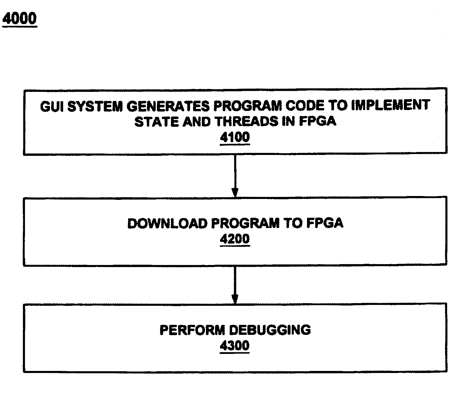
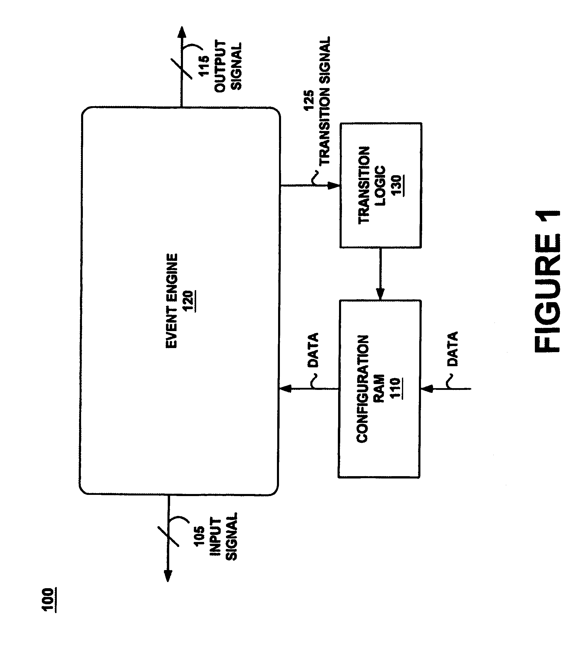
[0044]Embodiments of the present invention are directed to a graphical user interface (GUI) for programming an event engine. The description of the GUI commences at Section II at FIG. 24. Presented first, Section I, A-D, FIGS. 1–23 represent a discussion of the event engine to provide context to the GUI discussion.

IA. Re-Configurable Event Engines

[0045]Embodiments of the present invention may be able to reconfigure an event en...


PUM


Abstract

Programming a plurality of states having respective threads is achieved by an event engine and a computer controlled GUI causing the event engine to monitor a signal and execute an action based thereon. The GUI programs an event and several states and causes the event engine to traverse between the states upon reaching the event. The GUI further programs a logic chain which unifies the threads. A method unifies several threads by selecting and executing a logic operation. The method further configures several states and causes traversing between them. The GUI may be deployed co-functionally with debuggers, logic analyzers, scopes, utilities, and software development tools. The results of the GUI are automatically transformed into program code which programs the event engine to operate during debug of a device under test by monitoring for events and taking action based thereon.

Description

FIELD OF THE INVENTION[0001]The present invention relates to the field of testing electronic devices. Specifically, embodiments of the present invention relates to a graphical user interface with logic unifying functions.BACKGROUND ART[0002]Logic analyzers and in-circuit emulators have been used for many years by software and hardware developers to help diagnose and debug hardware and software. Such devices may be able to monitor and analyze various circuit and software conditions during debugging and testing of the design. For example, they may store trace information, such as time stamps, register values, data memory content, etc., which may be later analyzed. They may also provide various configurable breakpoints, which allow the designer to analyze the state of the design at a point in its operation by stopping operation when a specified condition occurs. The breakpoints may be based on a series of conditions that must happen before the operation is stopped.[0003]For example, co...

Claims


Application Information

Patent Timeline
Patent Type & Authority Patents(United States)
IPC IPC(8): G06F9/44
CPCG06F11/3664
Inventor ANDERSON, DOUGLASROE, STEVENNEMECEK, CRAIG
Owner MONTEREY RES LLC
Why Eureka
Try Eureka