Machine tool

a technology of machine tools and tools, applied in the field of machine tools, can solve the problems of affecting the operation of the machine, so as to facilitate the suppression of chatter vibrations, prevent problems, and facilitate the operation of the main spindle rotation speed of the first cutting at the start of machining

Active Publication Date: 2014-05-01
OKUMA CORP +1
View PDF3 Cites 9 Cited by
  • Summary
  • Abstract
  • Description
  • Claims
  • Application Information

AI Technical Summary

Benefits of technology

[0011]According to the present invention, the machine tool includes the specific-rotation-speed computing section that decides whether the rotation speed in a first tool pass in the threading process should be the high rotation speed or the low rotation speed so that cutting in a specific tool pass is performed at the high rotation speed. Accordingly, if, e.g., such a specific tool pass that tends to cause chatter vibrations is known, cutting in the specific tool pass can be easily performed at the high rotation speed, which further facilitates suppression of chatter vibrations.
[0012]According to the second aspect of the present invention, cutting in the last tool pass can be easily and reliably performed at the high rotation speed. This can reliably prevent problems due to cutting in the last tool pass at the low rotation speed, such as degradation in cutting surface accuracy.

Problems solved by technology

When machining is performed with a machine tool (in particular, machining of a workpiece with low rigidity or machining using a tool with low rigidity), strong vibrations known as chatter vibrations are often generated during machining.
Such chatter vibrations cause problems such as a so-called chatter mark on the cutting surface, chipping of the tool, etc.
However, in the case of changing the main spindle rotation speed in every plural passes, it is difficult to know whether the main spindle rotation speed of the first cutting at the start of machining should be the low rotation speed or the high rotation speed.
Accordingly, cutting in the specific tool pass or the last tool pass may be performed at the low rotation speed, which may hinder effective suppression of chatter vibrations or degrade cutting surface accuracy.

Method used


Image

  • Machine tool
  • Machine tool
  • Machine tool

Examples


Embodiment Construction

[0019]A machine tool according to an embodiment of the present invention will be described in detail with reference to the accompanying drawings.

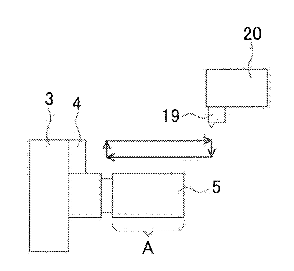
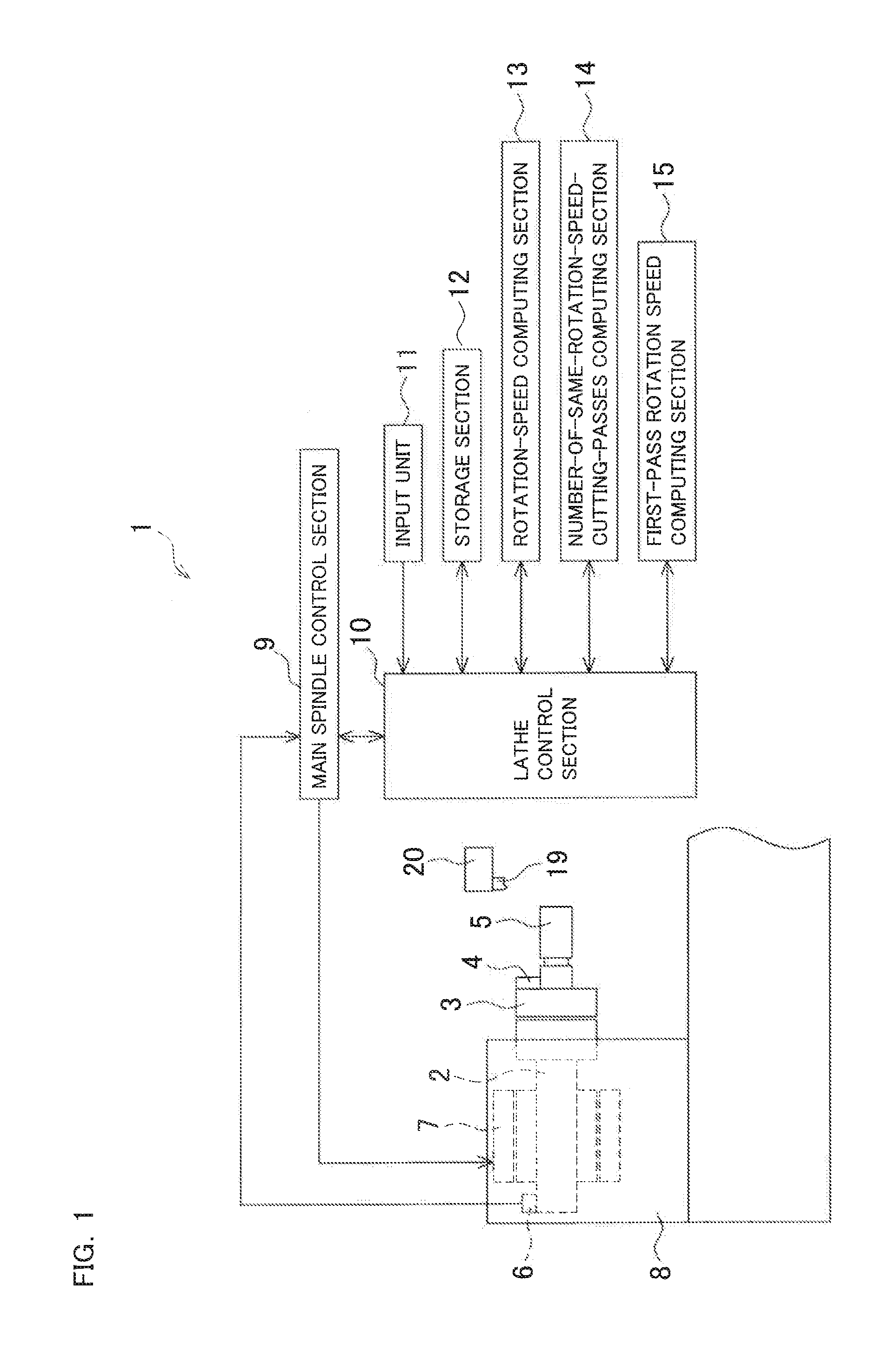
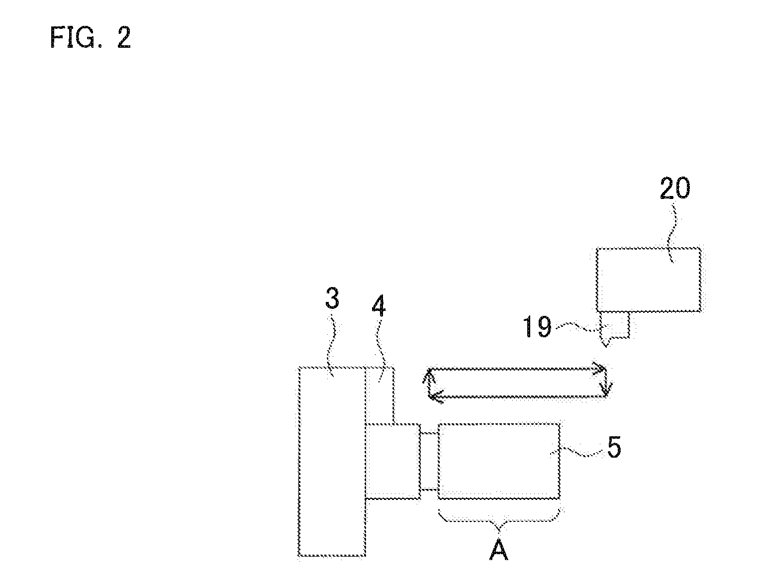
[0020]First, the overall configuration of a lathe 1 will be described with reference to FIG. 1. The lathe 1 includes a chuck 3 having a pawl 4 at the distal end of a main spindle 2, and is capable of holding a shaft-shaped workpiece 5 by the chuck 3. A motor 7 that rotates the main spindle 2 and an encoder 6 that detects the rotation speed of the main spindle 2 are contained in a headstock 8 that supports the main spindle 2 such that the main spindle 2 rotates.

[0021]A main spindle control section 9 monitors the rotation speed of the main spindle 2 by the encoder 6 and controls the rotation speed of the main spindle 2. A lathe control section 10 controls the overall behavior of the lathe 1, and is connected to the main spindle control section 9, an input unit 11, a storage section 12, a rotation-speed computing section (hereinafter referred ...


PUM

PropertyMeasurementUnit
regenerative widthaaaaaaaaaa
widthaaaaaaaaaa
rotation speedaaaaaaaaaa

Abstract

A machine tool includes a first-pass rotation speed computing section. The first-pass rotation speed computing section automatically decides whether the main spindle rotation speed in the first pass should be a high rotation speed or a low rotation speed so that cutting in the last tool pass is performed at the high rotation speed. Thus, cutting of the last tool pass at the low rotation speed can be reliably prevented.

Description

BACKGROUND OF THE INVENTION[0001]This application claims the benefit of Japanese Patent Application Number 2012-239393 filed on Oct. 30, 2012, the entirety of which is incorporated by reference.[0002]1. Technical Field[0003]The present invention relates to machine tools such as lathes capable of performing, e.g., a threading process.[0004]2. Background Art[0005]When machining is performed with a machine tool (in particular, machining of a workpiece with low rigidity or machining using a tool with low rigidity), strong vibrations known as chatter vibrations are often generated during machining. Such chatter vibrations cause problems such as a so-called chatter mark on the cutting surface, chipping of the tool, etc. As a solution to such problems, a technique has been devised which suppresses the chatter vibrations by changing the main spindle rotation speed during a threading cycle, as disclosed in, e.g., Japanese Patent Application Publication No. 2004-209558 (JP 2004-209558 A).[000...

Claims


Application Information

Patent Timeline
Patent Type & Authority Applications(United States)
IPC IPC(8): G05B19/18
CPCG05B19/186B23G1/04B23G3/00G05B2219/49392
Inventor NISHIMURA, KOHEI
Owner OKUMA CORP
Why Eureka
Try Eureka