
Terminal with wire, manufacturing method of terminal with wire, and wire harness

a manufacturing method and wire harness technology, applied in the direction of coupling contact member manufacturing, coupling device connection, contact member manufacturing, etc., can solve the problems of corrosion of the contact portion between an aluminum material and a copper material, the oxide film of the element wire of the conductor can be destructed, and the electrolytic corrosion of the contact portion can occur. , to achieve the effect of effective providing the terminal with the wire, high anti-corrosion property, and excellent manufacturability

Active Publication Date: 2018-04-24
YAZAKI CORP
View PDF30 Cites 10 Cited by
  • Summary
  • Abstract
  • Description
  • Claims
  • Application Information

AI Technical Summary

Benefits of technology

The invention provides a wire-terminal connection that uses a sealing material that can be quickly cured when exposed to ultraviolet rays. The sealing material also emits light, making it easy to determine its quality and even detect any disturbances. This is particularly useful in situations where there is a lot of light. The invention also includes a wire harness that uses the described terminals and wires, which are efficient and reliable.

Problems solved by technology

According to the method, the oxide films of element wires of the conductor can be destructed by strongly caulking the conductor of the aluminum wire.
However, it is known that, when moisture is present in the contact portion, both aluminum and copper are ionized and melt into the water so as to cause a potential difference therebetween.
Therefore, electrolytic corrosion occurs in a contact portion between an aluminum material and a copper material (in other words, the contact portion of heterogeneous metals).

Method used


Image

  • Terminal with wire, manufacturing method of terminal with wire, and wire harness
  • Terminal with wire, manufacturing method of terminal with wire, and wire harness
  • Terminal with wire, manufacturing method of terminal with wire, and wire harness

Examples


examples

[Examples]

[0120]Hereinafter, examples of the second embodiment will be described with reference to the drawings. Further, the following examples of the second embodiment are different from those of the first embodiment in the anticorrosion material of the anticorrosion portion and the anticorrosion material curing process in the manufacturing method. On the other hand, the terminal with the wire, the manufacturing method, and the basic configuration of the wire harness are equal to those of the examples of the first embodiment. In the following, the examples of the second embodiment will be described focusing on the differences from those of the first embodiment.

[0121]FIG. 10 is a perspective view of the terminal with the wire for describing the manufacturing method in the second embodiment of the invention, FIG. 11 is a cross-sectional view taken along a line A′-A′ of FIG. 10, and FIG. 12 is a diagram for describing a process of the manufacturing method in the second embodiment of ...


PUM


Abstract

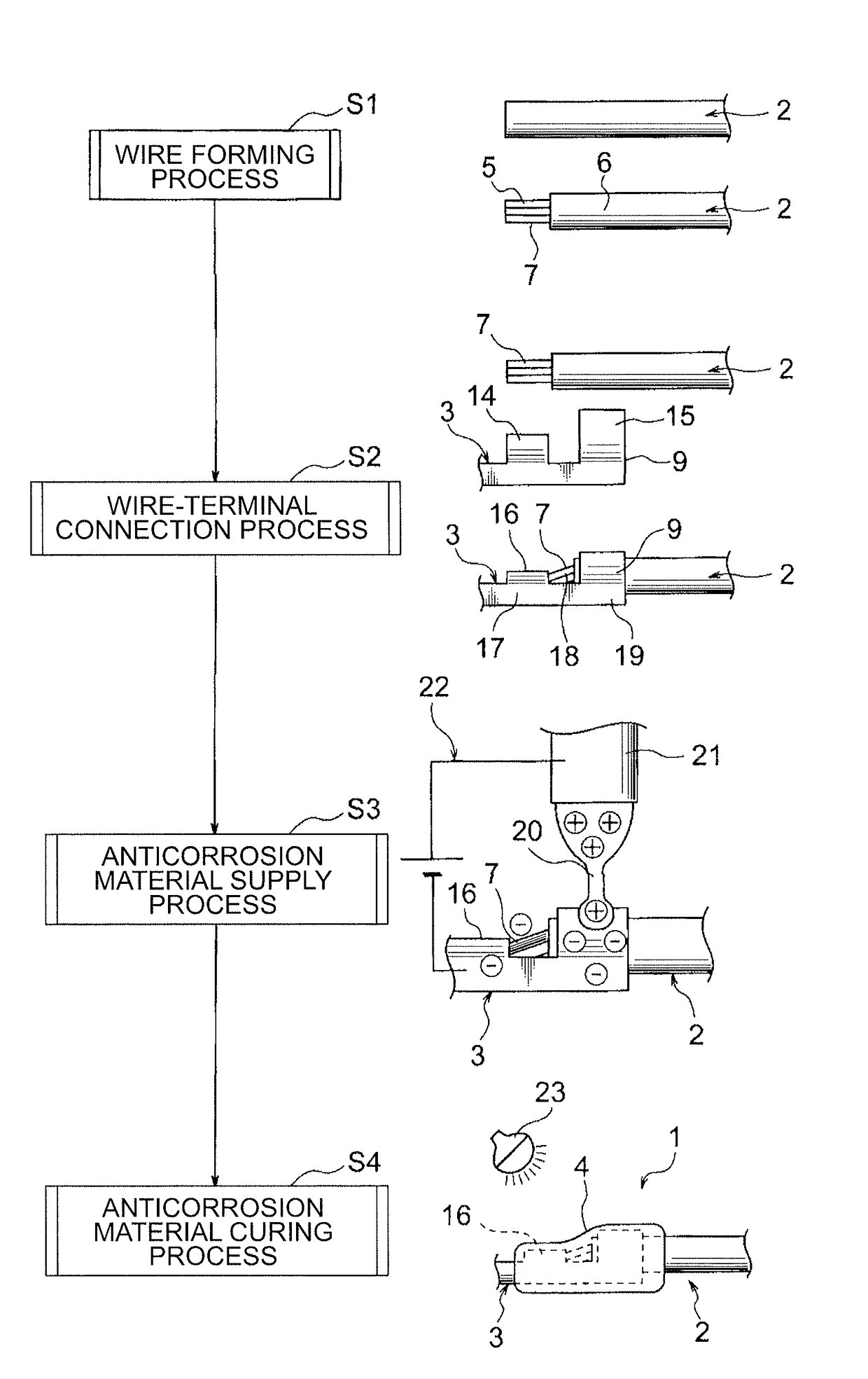
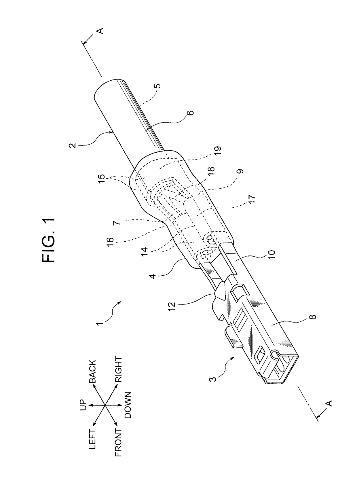
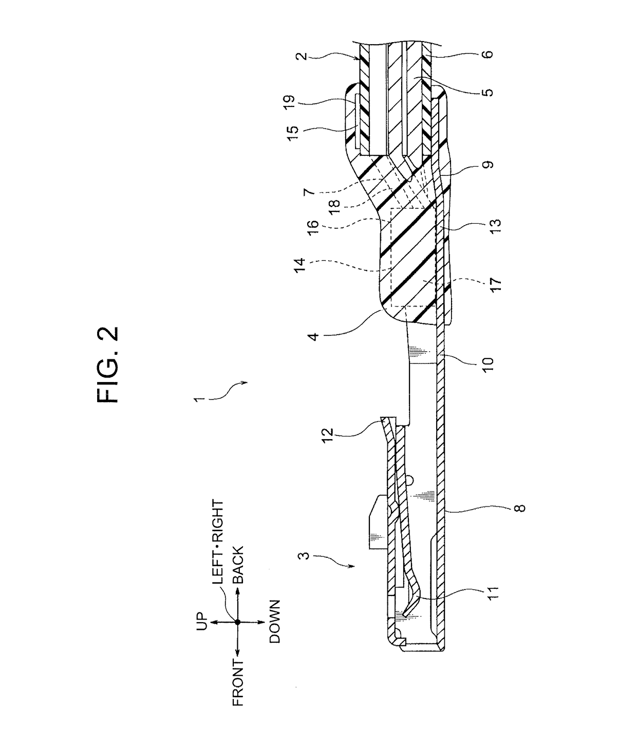
A terminal with a wire having a high sealing property, a manufacturing method thereof, and a wire harness are provided. The terminal with the wire includes an aluminum wire and a crimp terminal. A resin covering member is removed from the aluminum wire to form a conductor exposed portion (a wire forming process). The crimp terminal is connected to the conductor exposed portion to form a wire-terminal connection portion (a wire-terminal connection process). Then, an anticorrosion portion is formed such that a voltage is applied between the crimp terminal and a metal nozzle and an electrified anticorrosion material is supplied from the metal nozzle to the wire-terminal connection portion in a state of being attracted (an anticorrosion material supply process). Further, the anticorrosion portion is formed by irradiating the anticorrosion material with an ultraviolet ray to be UV-cured (an anticorrosion material curing process).

Description

BACKGROUND[0001]Technical Field[0002]The present invention relates to a terminal with a wire which includes an anticorrosion portion formed at a connection portion of heterogeneous metals in a wire and terminal metal fitting, a manufacturing method of the terminal with the wire, and a wire harness containing the terminal with the wire.[0003]Related Art[0004]For example, a wire harness is routed in a vehicle in order to electrically connect devices mounted in the vehicle. The wire harness is configured to include wire bundles and various types of connectors provided at the ends of the wire bundles. The connector of the wire harness is configured to include an insulative connector housing and a plurality of conductive terminal metal fittings contained in a terminal housing chamber of the connector housing. The terminal metal fitting is provided at the end of a wire of the wire bundle. As the wire, a copper wire (a conductor is made of copper or copper alloy in a twisted form) is gener...

Claims


Application Information

Patent Timeline
Patent Type & Authority Patents(United States)
IPC IPC(8): H01R43/20H01R13/52H01R13/11H01R4/70H01R43/18H01R43/16
CPCH01R4/70H01R43/20H01R13/52H01R13/113H01R4/62H01R13/02H01R43/00
Inventor MIYAKAWA, DAISUKEKAWAKAMI, TOMONORI
Owner YAZAKI CORP
Learn More