Light source apparatus

a technology of light source and light source cluster, which is applied in the direction of lighting and heating apparatus, semiconductor devices of light sources, instruments, etc., can solve the problems of achieve the effect of reducing color unevenness and the color unevenness between the light emission clusters caused when local dimming control is performed

Active Publication Date: 2014-11-13
CANON KK
View PDF1 Cites 6 Cited by
  • Summary
  • Abstract
  • Description
  • Claims
  • Application Information

AI Technical Summary

Benefits of technology

[0009]The technology disclosed in Japanese Patent Application Laid-open No. 2008-034361 is aimed at reducing color unevenness caused at the upper, lower, and corner parts of a screen when all the light emission clusters are caused to emit light with the same light emission brightness but does not consider color unevenness caused when the local dimming control is performed. In addition, the technology disclosed in Japanese Patent Application Laid-open No. 2008-003220 is aimed at reducing, rather than the color unevenness caused when the local dimming control is performed, color unevenness caused when the composition (color mixture) of the light emitted from the LEDs of the respective colors is different between central and outer edge parts. Therefore, even with the technology disclosed in Japanese Patent Application Laid-open No. 2008-034361 and Japanese Patent Application Laid-open No. 2008-003220, the color unevenness between the light emission clusters caused when the local dimming control is performed may not be reduced.
[0010]The present invention provides a light source apparatus capable of reducing the color unevenness between a plurality of light emission clusters caused when local dimming control is performed by the light source apparatus including the plurality of light emission clusters each having light sources of a plurality of colors.

Problems solved by technology

However, when the local dimming control is performed by the backlight apparatus including the plurality of light emission clusters each having the LEDs of the plurality of colors, color unevenness is caused between the light emission clusters due to a difference in the light emission brightness between the light emission clusters.
Therefore, even with the technology disclosed in Japanese Patent Application Laid-open No. 2008-034361 and Japanese Patent Application Laid-open No. 2008-003220, the color unevenness between the light emission clusters caused when the local dimming control is performed may not be reduced.

Method used


Image

  • Light source apparatus
  • Light source apparatus
  • Light source apparatus

Examples


first embodiment

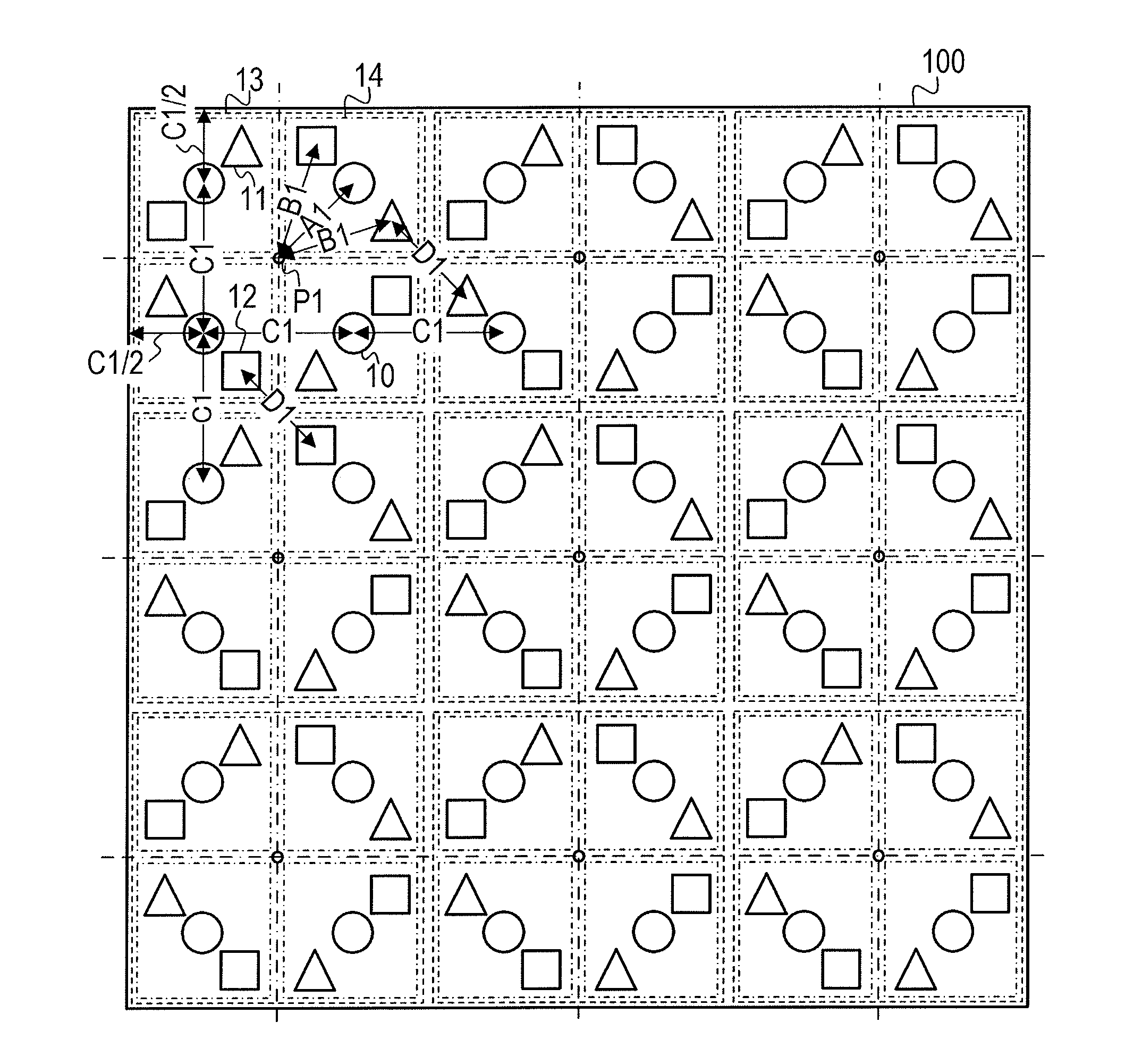
[0030]Hereinafter, a description will be given of a light source apparatus according to a first embodiment of the present invention. The light source apparatus according to the embodiment is a light source apparatus capable of performing local dimming control. The light source apparatus according to the embodiment may be used as, for example, a backlight apparatus for a liquid crystal display unit.

[0031]Note that the light source apparatus according to the embodiment is not limited to a backlight apparatus. For example, the light source apparatus according to the embodiment may be used as the light source apparatus of a display unit (such as an advertisement sign unit and a sign display unit) that allows light to pass through to display an image. In addition, the light source apparatus according to the embodiment may be used as the light source apparatus of a unit other than a display unit such as indoor lighting and a street light.

[0032]FIG. 1 shows an example of the configuration ...

second embodiment

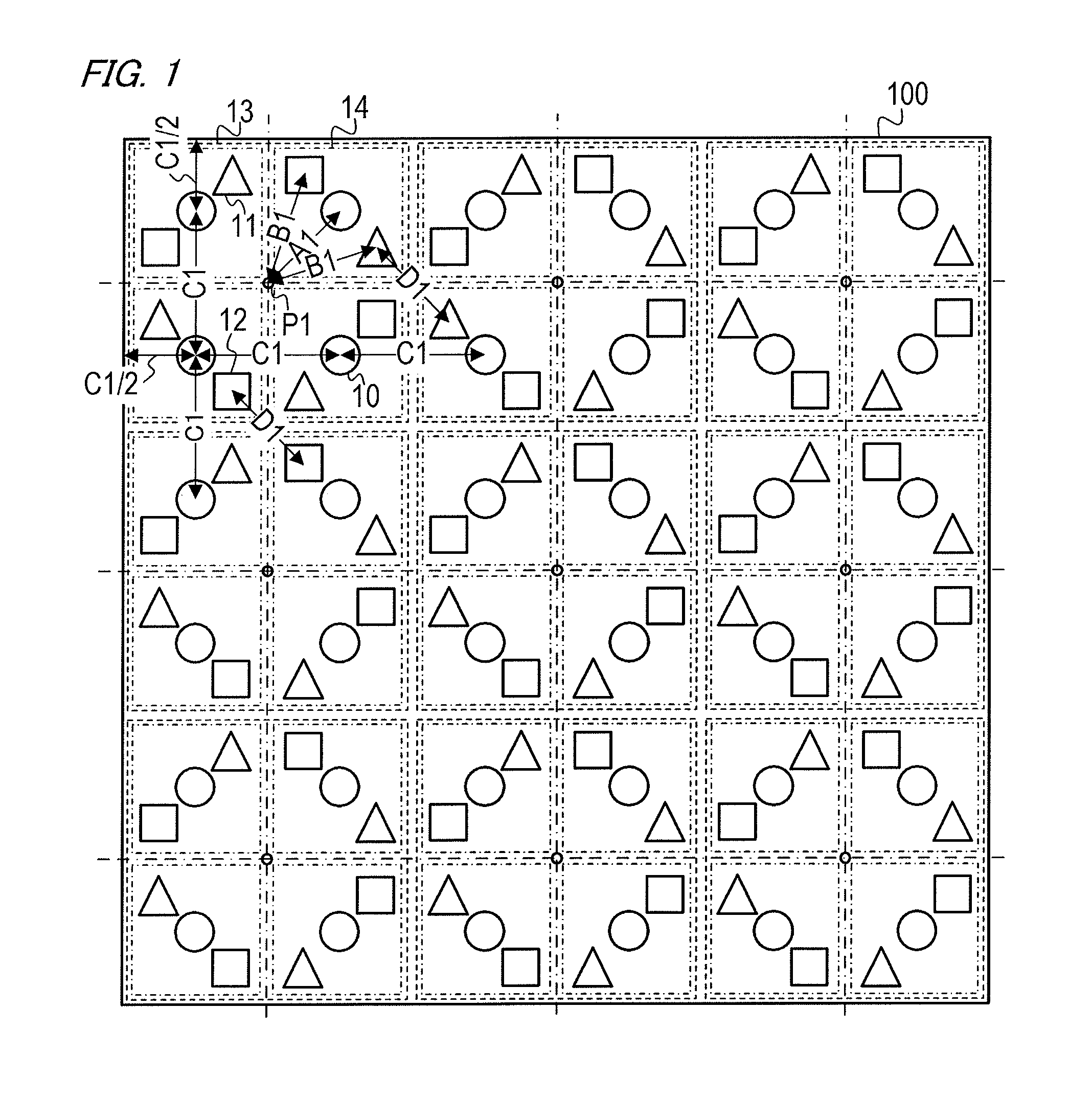
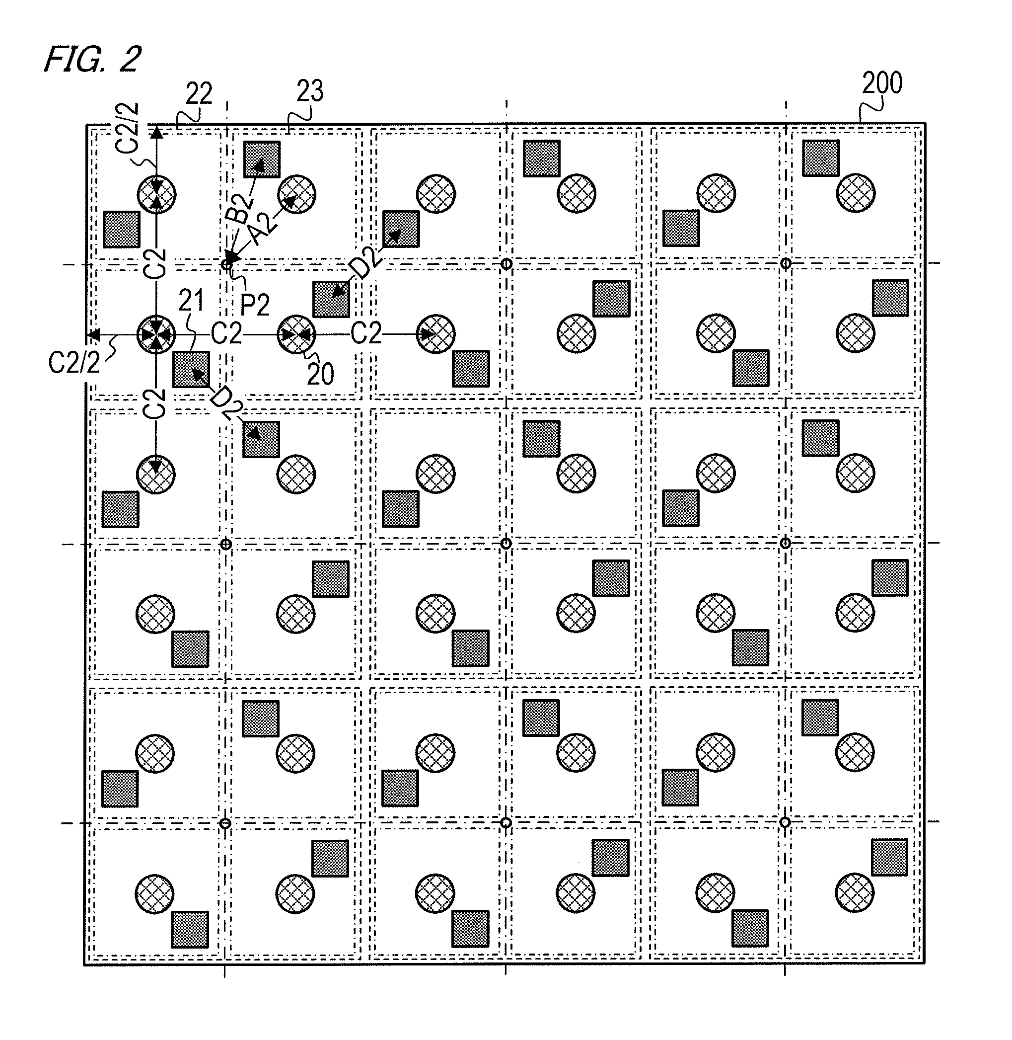
[0066]Hereinafter, a description will be given of a light source apparatus according to a second embodiment of the present invention. The first embodiment describes the configuration in which the three types of the light sources of the green, red, and blue LEDs are used. The embodiment will describe a configuration in which two types of light sources are used. Specifically, the description will be given of the configuration in which cyan LEDs (C light sources) serving as light sources that emit the light of a cyan color and red LEDs (R light sources) serving as light sources that emit the light of a red color are used. A difference in the brightness of the red color is more easily perceived than a difference in the brightness of the cyan color. Therefore, in the embodiment, the cyan color is a first color, the red color is a second color, the cyan LED is a first light source, and the red LED is a second light source.

[0067]Note that the two types of the light sources are not limited ...


PUM


Abstract

A light source apparatus includes a plurality of light emission clusters arranged in a matrix pattern, wherein the light emission cluster has four sub light emission clusters of two rows and two columns, the sub light emission cluster has a plurality of light sources, the plurality of light sources having a first light source that emits light of a first color and a second light source that emits light of a second color, a difference in brightness of the second color being more easily perceived than a difference in brightness of the first color, and an interval between a center of the light emission cluster and the second light source of the light emission cluster is greater than or equal to an interval between the center of the light emission cluster and the first light source of the light emission cluster.

Description

BACKGROUND OF THE INVENTION[0001]1. Field of the Invention[0002]The present invention relates to a light source apparatus.[0003]2. Description of the Related Art[0004]Conventionally, cold cathode fluorescent lamps (CCFLs) have been used as the light sources of backlight apparatuses for liquid crystal display units. In recent years, however, backlight apparatuses using light emitting diodes (LEDs) as the light sources thereof have become widespread. From the standpoint that LEDs are point light sources, it is necessary to consider, when using the LEDs as the light sources of backlight apparatuses, the arrangement of the LEDs, the diffusion structure of light, the reflection structure of light, or the like to reduce brightness unevenness and color unevenness. Since brightness unevenness and color unevenness are easily caused in backlight apparatuses using LEDs of a plurality of colors such as red, green, and blue colors, consideration is particularly given to the arrangement of the LE...

Claims


Application Information

Patent Timeline
Patent Type & Authority Applications(United States)
IPC IPC(8): F21V23/04
CPCF21V23/04F21Y2115/10F21Y2107/50F21Y2105/12G02F1/133603G02F1/133613
Inventor MATSUURA, YASUHIRO
Owner CANON KK
Why Eureka
Try Eureka