Hands-Free Safety Gate

a safety gate and hand-free technology, applied in the field of hand-free safety gates, can solve the problem that the actuator is unable to move the rod substantially vertically, and achieve the effect of reducing the risk of accidents

Inactive Publication Date: 2015-01-29
SOUSA MARK J +3
View PDF19 Cites 20 Cited by
  • Summary
  • Abstract
  • Description
  • Claims
  • Application Information

AI Technical Summary

Benefits of technology

[0003]In accordance with one embodiment of the invention, a child safety gate includes a frame having first and second sides configured to be removably mounted to opposing sides of a passageway. The gate further includes a door pivotably coupled to the first side and releasably coupled to the second side and a release mechanism coupled to the first side of the frame and pivotably coupled to the door. The release mechanism includes a foot pedal and is configured to move the door from a closed and locked position to an open position when the foot pedal is sufficiently actuated.
[0004]In some embodiments, the child safety gate may be releasably coupled to the second side of the frame by a latch mechanism. The latch mechanism may include a hand release mechanism configured to move the door from the locked position to an unlocked position. The hand release mechanism may include a slider configured to move from a locked position to a released position, a rod configured to move in a substantially vertical direction, and an actuator movably coupled to the rod. The actuator may move the rod in the substantially vertical direction when the slider is in the released position. In addition, the actuator may be unable to move the rod in the substantially vertical direction when the slider is in the locked position. The release mechanism may be configured to move the door in a substantially vertical direction so as to allow the door to go from the locked position to an unlocked position. The release mechanism may include a spring configured to move the door from the open position to the closed and locked position. The frame may include a connecting member configured to couple the first side to the second side of the frame, and the release mechanism may be also coupled to the connecting member. The release mechanism may include two foot pedals disposed in opposing directions, and the second foot pedal may be configured to move the door from the closed and locked position to the open position when the second foot pedal is sufficiently actuated.

Problems solved by technology

In addition, the actuator may be unable to move the rod in the substantially vertical direction when the slider is in the locked position.

Method used


Image

  • Hands-Free Safety Gate
  • Hands-Free Safety Gate
  • Hands-Free Safety Gate

Examples


Embodiment Construction

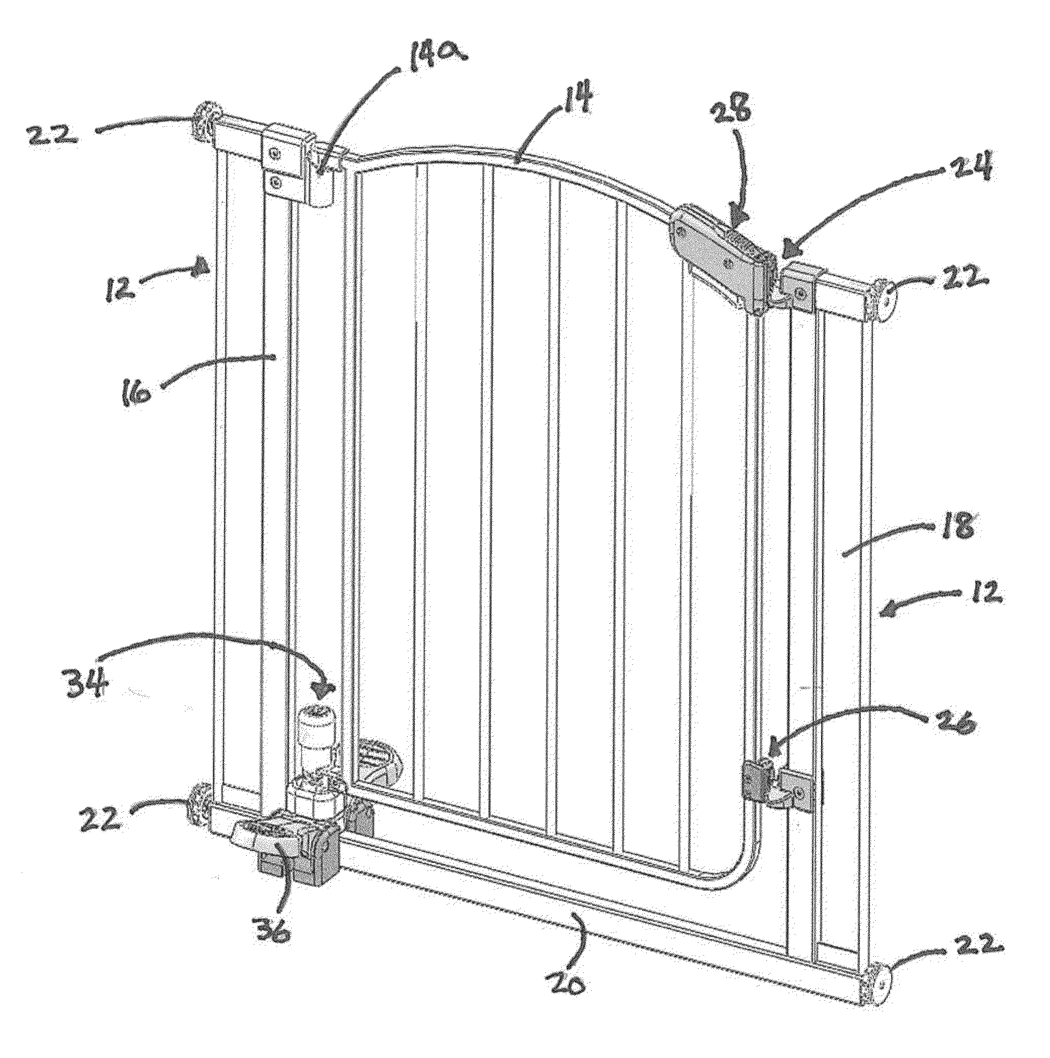
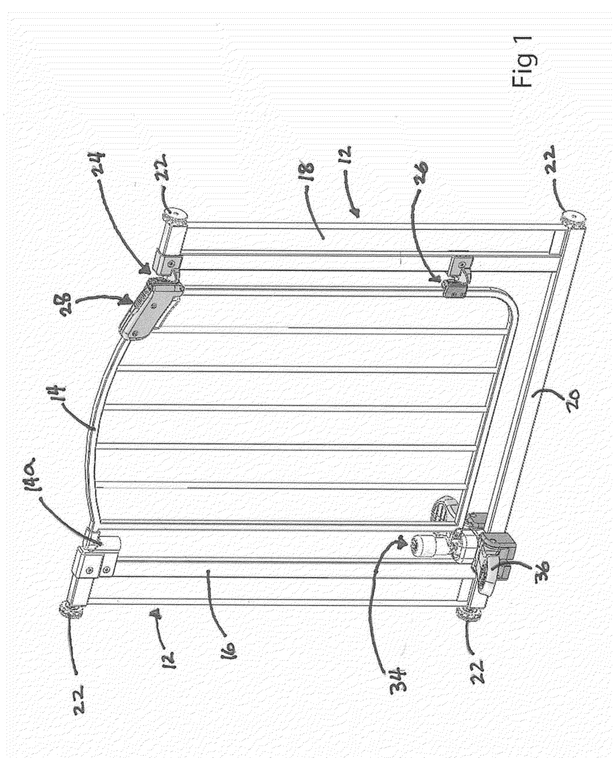
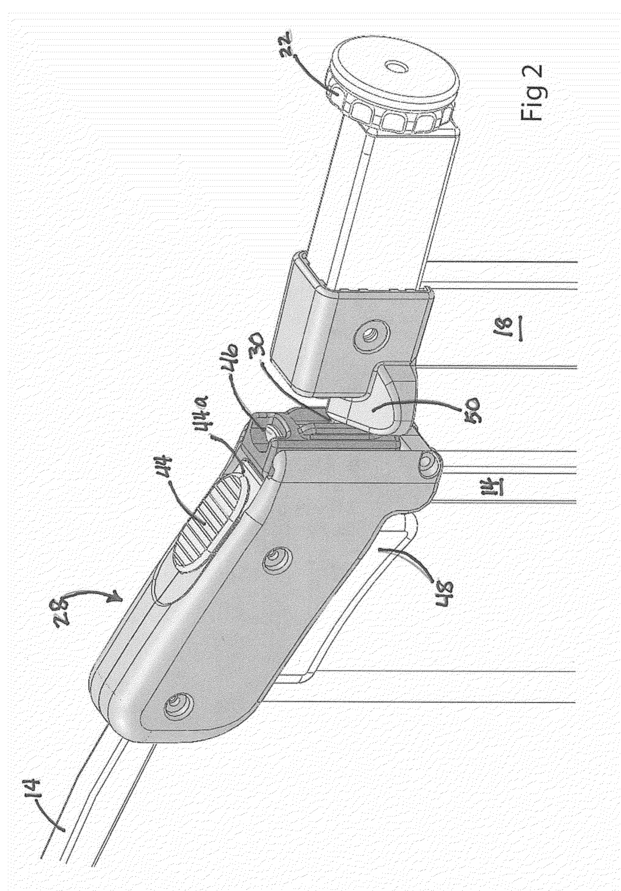
[0020]Various embodiments of the present invention provide a child safety gate that is capable of being opened without using the hands. The gate includes a frame configured to be removably mounted to opposing sides of a passageway, a door pivotably coupled to one side of the frame and releasably coupled to the other side of the frame, and a release mechanism coupled to one side of the frame and pivotably coupled to the door. The release mechanism includes a foot pedal and is configured to move the door from a closed and locked position to an open position when the foot pedal is sufficiently depressed or actuated. In addition, the gate includes a hand release mechanism so that the gate may be unlocked and opened by hand without using the release mechanism and its foot pedal. The safety gate prevents infants or toddlers from leaving a designated area while permitting relatively easy access through the passageway for adults. Details of illustrative embodiments are discussed below.

[0021...


PUM


Abstract

A child safety gate includes a frame having a first side and a second side configured to be removably mounted to opposing sides of a passageway. The gate further includes a door pivotably coupled to the first side and releasably coupled to the second side and a release mechanism coupled to the first side of the frame and pivotably coupled to the door. The release mechanism includes a foot pedal and is configured to move the door from a closed and locked position to an open position when the foot pedal is sufficiently actuated.

Description

TECHNICAL FIELD[0001]The invention relates to child safety gates, and more specifically to child safety gates that are capable of being opened without using the hands.BACKGROUND[0002]Child safety gates are used to block passageways so that infants and toddlers are prevented from leaving designated areas or from accessing unsupervised areas. The gates, however, need to allow relatively easy access through the passageway for authorized individuals such as older children or adults. In some cases, the safety gates are difficult to open or require one or two hands to remove the barrier to the passageway, open the door or re-latch it closed.SUMMARY OF THE INVENTION[0003]In accordance with one embodiment of the invention, a child safety gate includes a frame having first and second sides configured to be removably mounted to opposing sides of a passageway. The gate further includes a door pivotably coupled to the first side and releasably coupled to the second side and a release mechanism ...

Claims


Application Information

Patent Timeline
Patent Type & Authority Applications(United States)
IPC IPC(8): E06B11/02E05B65/00E06B9/04
CPCE06B11/022E05B65/0014E05B65/0007E06B9/04E06B2009/002E05B17/2038E05B53/001E05C9/1808E05C9/185E05C19/006
Inventor SOUSA, MARK J.SUNDBERG, BRIANBRIDEN, CHRISTOPHER C.TOROSIAN, STEVEN L.
Owner SOUSA MARK J
Why Eureka
Try Eureka