Methods and systems for egr control

a technology of egr control and control system, applied in the direction of electric control, machines/engines, mechanical equipment, etc., can solve the problems of increasing the potential for compressor surge, increasing the cost of components, and the need for an additional throttle, so as to improve the peak power output, improve the effect of exhaust emissions and increase the dilution of the engin

Active Publication Date: 2015-02-19
FORD GLOBAL TECH LLC
View PDF3 Cites 45 Cited by
  • Summary
  • Abstract
  • Description
  • Claims
  • Application Information

AI Technical Summary

Benefits of technology

[0002]Engine systems may be configured with a boosting device, such as a turbocharger, for providing a boosted aircharge and improving peak power outputs. Therein a turbine is rotated using energy from an exhaust flow, the turbine then driving a compressor which delivers a boosted aircharge to the engine intake. To improve exhaust emissions, engine systems may also be configured with exhaust gas recirculation (EGR) sy...

Problems solved by technology

However, the inventors herein have recognized potential issues with such an approach.
As one example, the low pressure at the compressor inlet increases the potential for compressor surge.
In addition, durability concerns may be raised if oil ...

Method used


Image

  • Methods and systems for egr control
  • Methods and systems for egr control
  • Methods and systems for egr control

Examples


Embodiment Construction

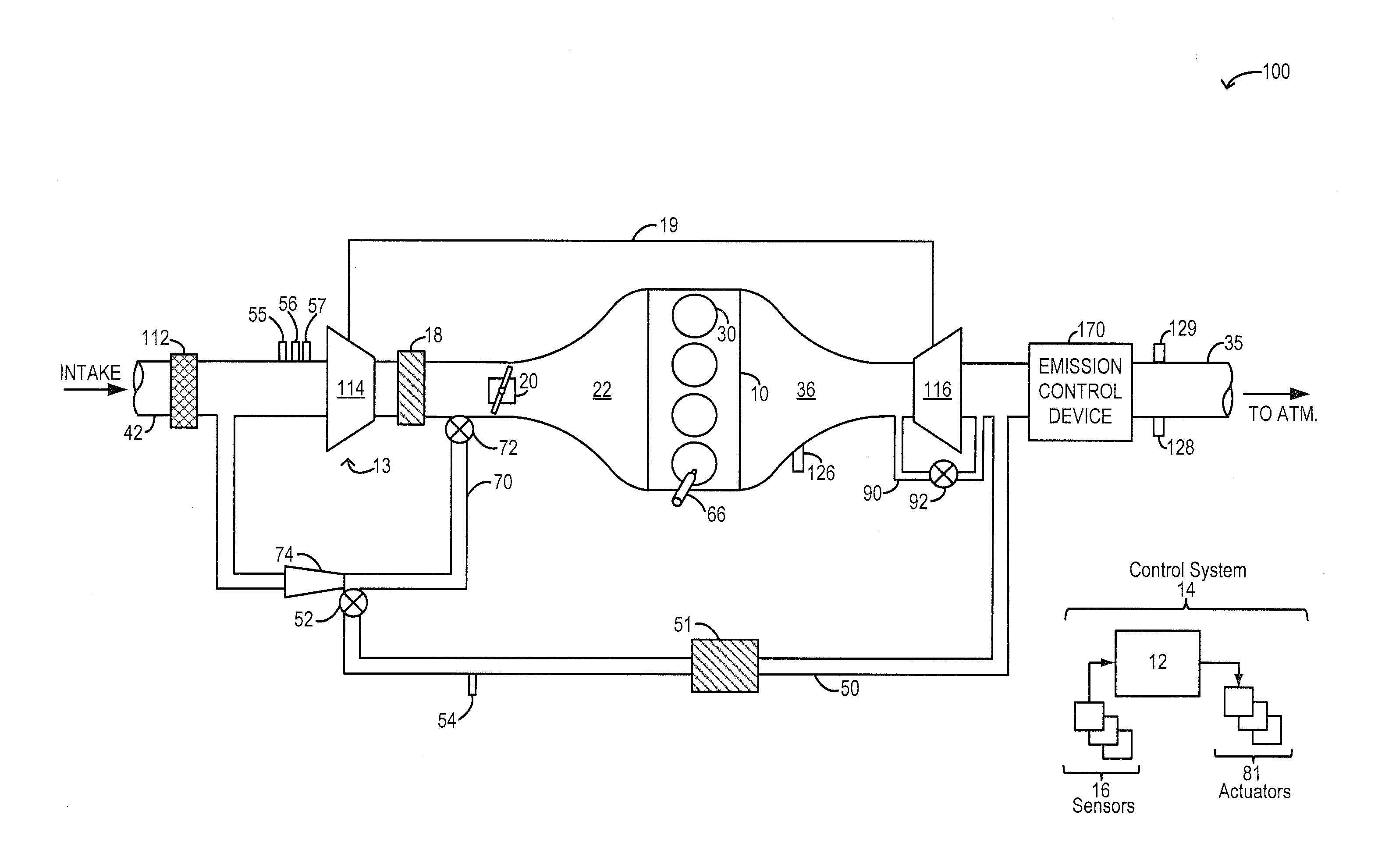
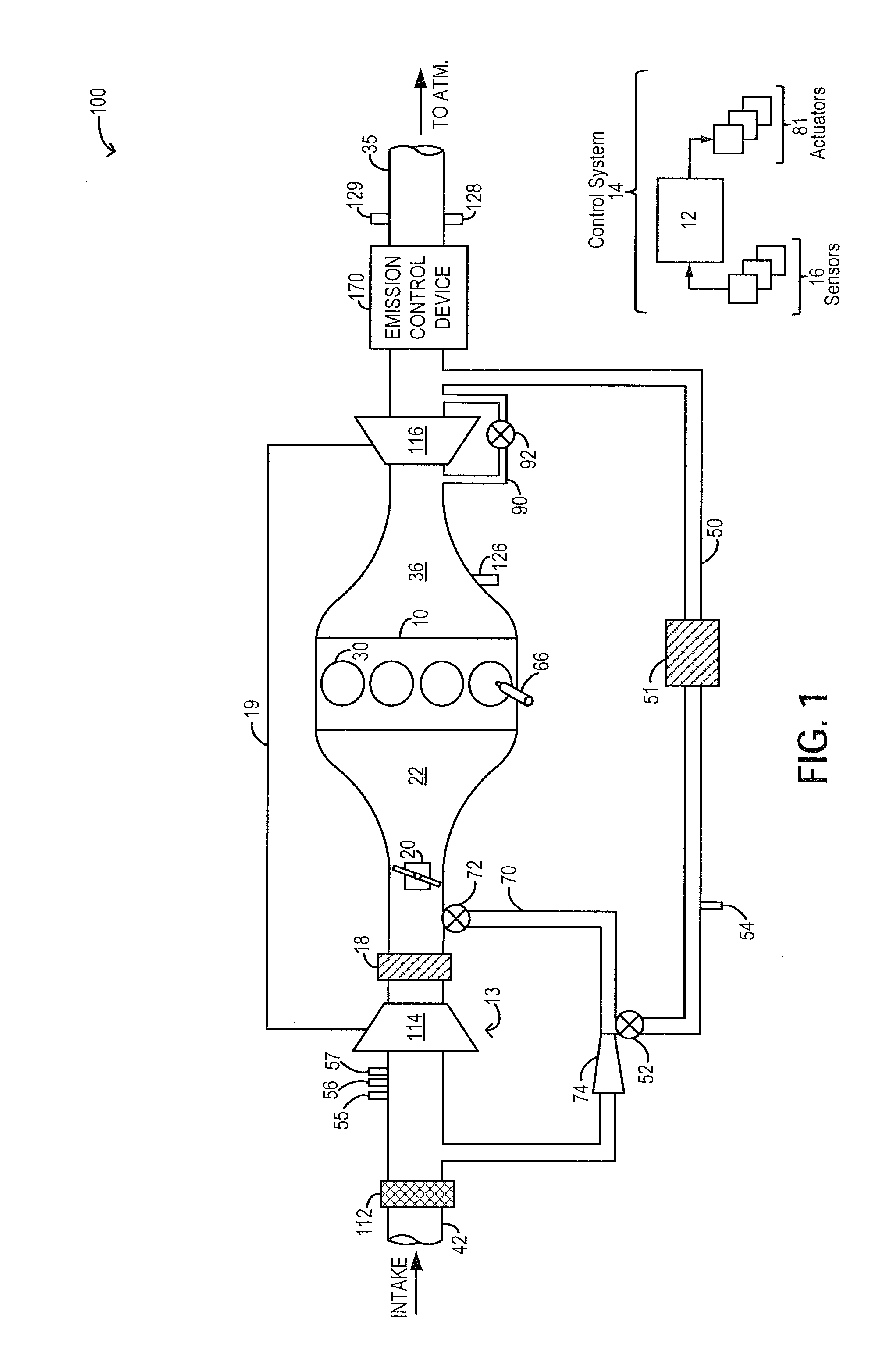
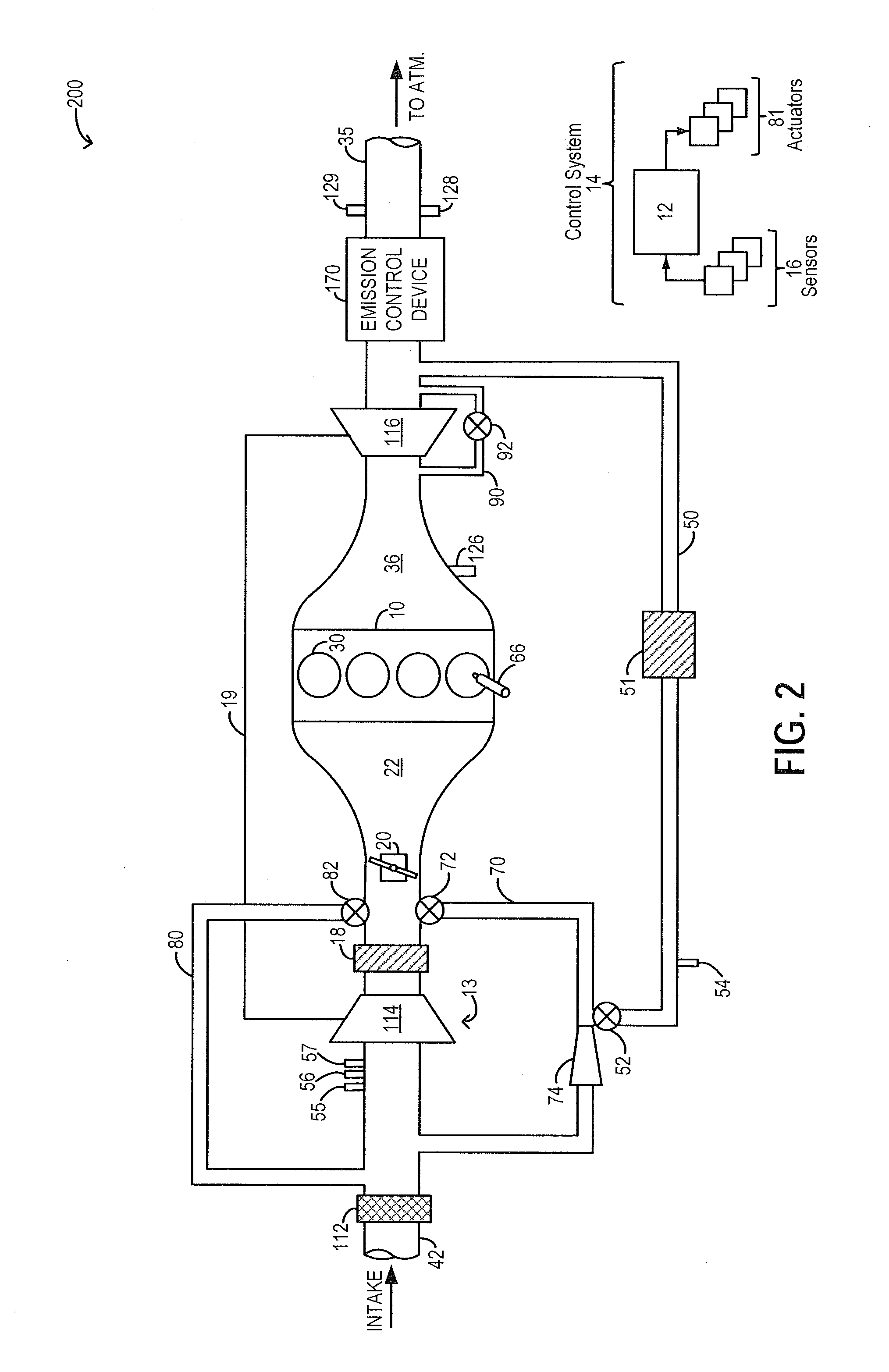
[0014]The following description relates to systems and methods for using compressor recirculation flow to draw in low pressure EGR into an engine system, such as the system of FIGS. 1-2. A controller may be configured to perform a control routine, such as the routine of FIGS. 4-5, to adjust an amount of cooled compressor recirculation flow directed from downstream of a charge air cooler to a compressor inlet via a venturi (FIG. 3) based on a desired EGR rate. By flowing the compressor recirculation flow through the venturi, a vacuum can be generated at the venturi's neck. The generated vacuum can then be used to enhance EGR flow drawn in from an EGR passage coupled to the compressor recirculation path at the venturi. An example compressor recirculation flow adjustment that may be used to draw in EGR are shown with reference to FIGS. 6-7. In this way, a carbureted flow of EGR can be provided while improving the margin to surge.

[0015]FIGS. 1-2 depict example embodiments of an engine s...


PUM


Abstract

Methods and systems are provided for using compressor recirculation flow via a venturi to enhance low pressure EGR flow. The opening of a compressor recirculation valve can be adjusted based on EGR flow demand to recirculate cooled compressed air through a venturi while generating vacuum for drawing EGR. The approach allows for concurrent EGR control and surge control.

Description

FIELD[0001]The present application relates to methods and systems for drawing in EGR through a compressor recirculation path including a venturi.BACKGROUND AND SUMMARY[0002]Engine systems may be configured with a boosting device, such as a turbocharger, for providing a boosted aircharge and improving peak power outputs. Therein a turbine is rotated using energy from an exhaust flow, the turbine then driving a compressor which delivers a boosted aircharge to the engine intake. To improve exhaust emissions, engine systems may also be configured with exhaust gas recirculation (EGR) systems wherein at least a portion of the exhaust gas is recirculated to the engine intake. For example, the EGR system may be a low-pressure EGR system (LP-EGR) that recirculates exhaust gas from downstream of an exhaust turbine to upstream of an intake compressor. EGR benefits include an increase in engine dilution, decrease in exhaust emissions, and improvements in fuel economy, especially at higher level...

Claims


Application Information

Patent Timeline
IPC IPC(8): F02M25/07
CPCF02M25/07F02D41/0007F02D41/0065F02M26/06F02M26/19F02M26/23Y02T10/12Y02T10/40
Inventor ULREY, JOSEPH NORMANMCCONVILLE, GREGORY PATRICKSTYLES, DANIEL JOSEPHPURSIFULL, ROSS DYKSTRASHELBY, MICHAEL HOWARD
Owner FORD GLOBAL TECH LLC
Why Eureka
Try Eureka