Methods and systems for surge control

a surge control and surge technology, applied in the direction of engine controllers, combustion engines, machines/engines, etc., can solve the problems of compressor surge, compressor surge, compressor forward flow through, etc., to reduce forward flow through compressors, improve peak power output, and reduce the effect of compressor forward flow

Active Publication Date: 2015-02-19
FORD GLOBAL TECH LLC
View PDF8 Cites 11 Cited by
  • Summary
  • Abstract
  • Description
  • Claims
  • Application Information

AI Technical Summary

Benefits of technology

[0002]Engine systems may be configured with boosting devices, such as turbochargers or superchargers, for providing a boosted aircharge and improving peak power outputs. The use of a compressor allows a smaller displacement engine to provide as much power as a larger displacement engine, but with additional fuel economy benefits. However, compressors are prone to surge. For example, when an operator tips-out of an accelerator pedal, an engine intake throttle closes, leading to reduced forward flow through the compressor, potentially causing compressor surge. Surge can lead to NVH issues such as undesirable noise from the engine intake system. As such, based on the state of the airflow and induction pressure, the compressor may be in a soft surge or hard surge operating region. During hard surge, the compressor allows air to momentarily backflow through the compressor resulting in rapid pressure oscillations. During soft surge, there is relatively smaller instability of compressor operation.

Problems solved by technology

However, compressors are prone to surge.
For example, when an operator tips-out of an accelerator pedal, an engine intake throttle closes, leading to reduced forward flow through the compressor, potentially causing compressor surge.
Surge can lead to NVH issues such as undesirable noise from the engine intake system.
During hard surge, the compressor allows air to momentarily backflow through the compressor resulting in rapid pressure oscillations.
However the inventors herein have identified potential issues with such systems.
In particular, if the valve is kept open (for example to alleviate surge tendencies before surge actually occurs), the compressor may not be able to provide the boost pressure required to meet the demanded engine torque.
Fuel economy is also degraded due to extra compressor work needing to be compensated by increased turbine work.
Also, energy may be required to hold the valve in the open position.
The inventors have realized that such an approach may actually lead to more energy being wasted.
This is because the margin to the surge limit may be smaller during steady-state conditions when the valve is kept closed, causing frequent surge, and requiring the valve to be frequently opened.
As such, this consumes energy.
This can degrade torque responsiveness.
In particular, if surge is avoided by opening the valve in response to a tip-out event which is soon followed by a tip-in event, it will take more time to recover boost pressure and provide engine torque than if the valve was not opened completely.
Further still, the valve of Blaiklock may not be able to address hard surge and soft surge equally well.
In particular, the large induction pressure reduction associated with the valve opening may decrease engine performance during the soft surge conditions if the valve is commanded open.
Further, the valve consumes substantially lower amounts of energy under most engine operating conditions.

Method used


Image

  • Methods and systems for surge control
  • Methods and systems for surge control
  • Methods and systems for surge control

Examples


embodiment 200

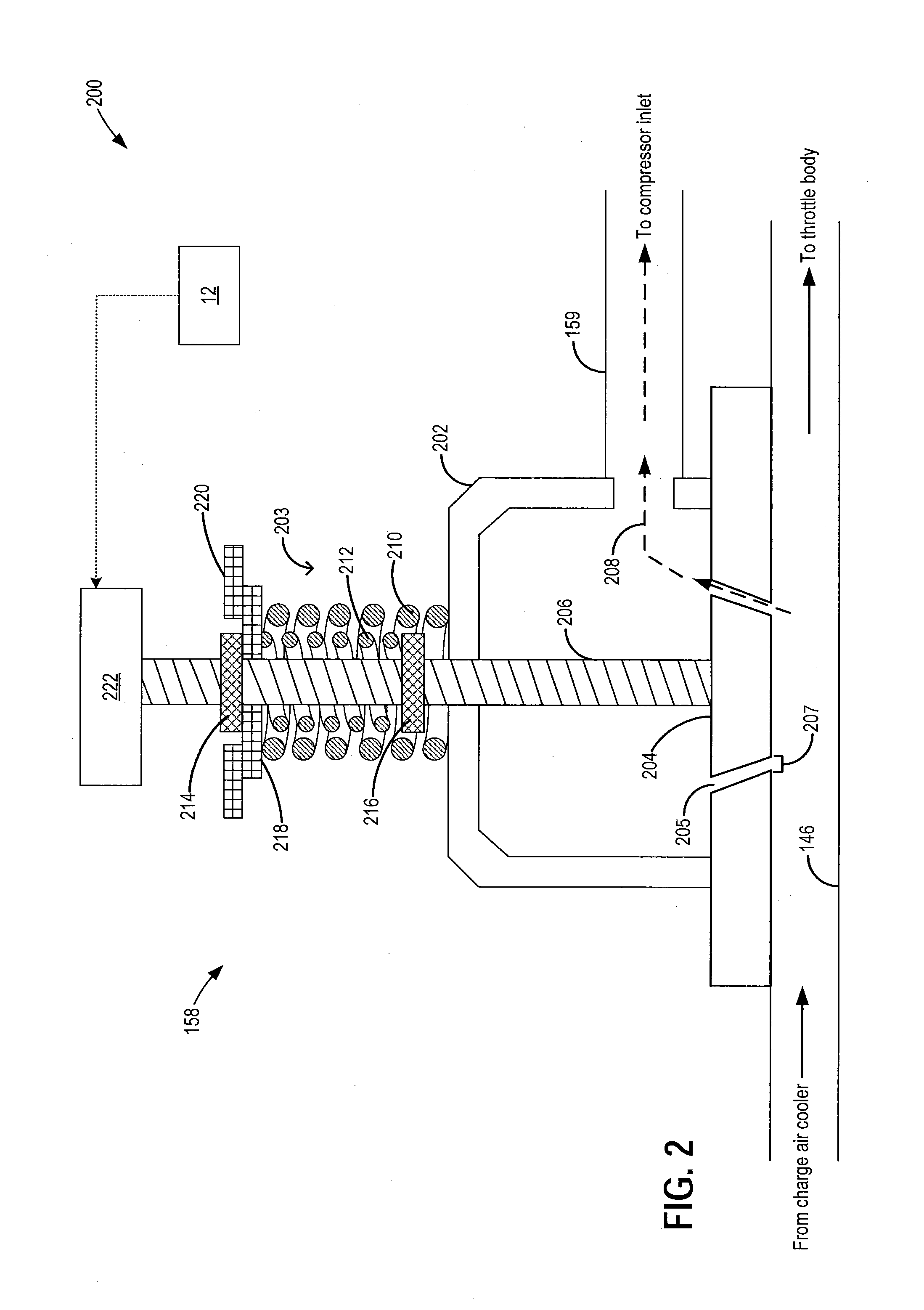
[0032]Embodiment 200 shows CRV 158 in the default semi-open state. Valve 158 may be coupled to boost intake chamber 146 such that in the semi-open state, a portion of cooled compressed air received from downstream of the charge air cooler can be recirculated into passage 159 for delivery to the compressor inlet.

[0033]Valve 158 may include a valve stem 206, a valve head 204, and a valve body 202. Valve head 204 may be displaced, for example raised or lowered, via valve stem 206, into valve opening 205 to vary an amount of airflow 208 through the valve. A pair of stepped ridges, including an upper ridge 214 and a lower ridge 216 may be coupled to valve stem 206. A moveable retaining washer 218 may also be coupled to valve stem 206. In the default position, moveable retaining washer 218 may be held immediately below upper ridge 214. An immoveable retaining washer 220 may be arranged in line with upper ridge 214 in the default position. By raising or lowering valve head 204 within valve...

embodiment 300

[0041]As shown, when in the default semi-open position, moveable retaining washer 218 may be in direct contact with immovable retaining washer 220 such that there is no gap between the washers. As a result of this configuration, inner spring 212 is held pre-compressed between lower ridge 216 and moveable retaining washer 218, while outer spring 210 is held pre-compressed between moveable retaining washer 218 and valve body 202. This configuration is also shown at embodiment 300 of FIG. 3.

embodiment 310

[0042]Embodiment 310 of FIG. 3 shows the valve in the fully-closed position. In this state, actuator 222 is energized to apply a downward force, or push, on the valve stem 206 and head 204. As a result of the downward force, upper ridge 214 is pushed downward, which impinges on moveable retaining washer 218 and pushes it downwards. As a result of the displacement of moveable retaining washer 218, a loading and compression of outer spring 210 is increased. In particular, a compression of outer spring 210 between valve body 202 and moveable retaining washer 218 is increased. At the same time, the compression of inner spring 212 is maintained due to no change in the displacement of moveable retaining washer 218 relative to lower ridge 216. The downward displacement of washer 218 increases a gap 209 between moveable retaining washer 218 and immoveable retaining washer 220, while applying a downward force that pushes valve head 204 further into opening 205. This reduces gap 207 and holds...


PUM


Abstract

Methods and systems are provided for improving a margin to surge. A compressor recirculation valve is held at a semi-open position during steady-state boosted engine operation and operation in a soft surge region. The valve is fully opened to reduce hard surge, or fully closed to meet a transient increase in boost demand.

Description

FIELD[0001]The present application relates to methods and systems for using compressor recirculation flow to improve surge control.BACKGROUND AND SUMMARY[0002]Engine systems may be configured with boosting devices, such as turbochargers or superchargers, for providing a boosted aircharge and improving peak power outputs. The use of a compressor allows a smaller displacement engine to provide as much power as a larger displacement engine, but with additional fuel economy benefits. However, compressors are prone to surge. For example, when an operator tips-out of an accelerator pedal, an engine intake throttle closes, leading to reduced forward flow through the compressor, potentially causing compressor surge. Surge can lead to NVH issues such as undesirable noise from the engine intake system. As such, based on the state of the airflow and induction pressure, the compressor may be in a soft surge or hard surge operating region. During hard surge, the compressor allows air to momentar...

Claims


Application Information

Patent Timeline
Patent Type & Authority Applications(United States)
IPC IPC(8): F02B47/08
CPCF02B47/08F02B2037/125F02B33/00F02B37/16Y02T10/12
Inventor MCCONVILLE, GREGORY PATRICKBUCKLAND, JULIA HELEN
Owner FORD GLOBAL TECH LLC
Why Eureka
Try Eureka