Boost apparatus with over-current and over-voltage protection functions

Inactive Publication Date: 2015-02-19
BEYOND INNOVATION TECH
View PDF14 Cites 3 Cited by
  • Summary
  • Abstract
  • Description
  • Claims
  • Application Information

AI Technical Summary

Benefits of technology

The invention provides a boost apparatus that can detect if there is an open circuit or short circuit on the output side of the boost apparatus. This helps to prevent damage to the components in the boost apparatus and the load. The boost apparatus includes a boost power conversion circuit and a control chip. The control chip generates a PWM signal to control the operation of the boost power conversion circuit, and stops outputting the PWM signal and enters a shutdown state when the diode is open or short-circuited, to protect the boost apparatus and the load from damage.

Problems solved by technology

However, when the diode located on an output side (or at an output terminal) of the boost apparatus is an open circuit or a short circuit, the power switch located on the power conversion path of the boost apparatus may be damaged (e.g., encountering the issue of short circuit), such that components in the boost apparatus and / or the load may be impaired, or the power source of a system having the boost apparatus applied encounters the issue of short circuit and is thus impaired.

Method used


Image

  • Boost apparatus with over-current and over-voltage protection functions
  • Boost apparatus with over-current and over-voltage protection functions

Examples


Embodiment Construction

[0018]Reference will now be made in detail to the embodiments of the invention. The embodiments are illustrated with the accompanying drawings. Wherever possible, the same reference numbers are used in the drawings and the description to refer to the same or like parts.

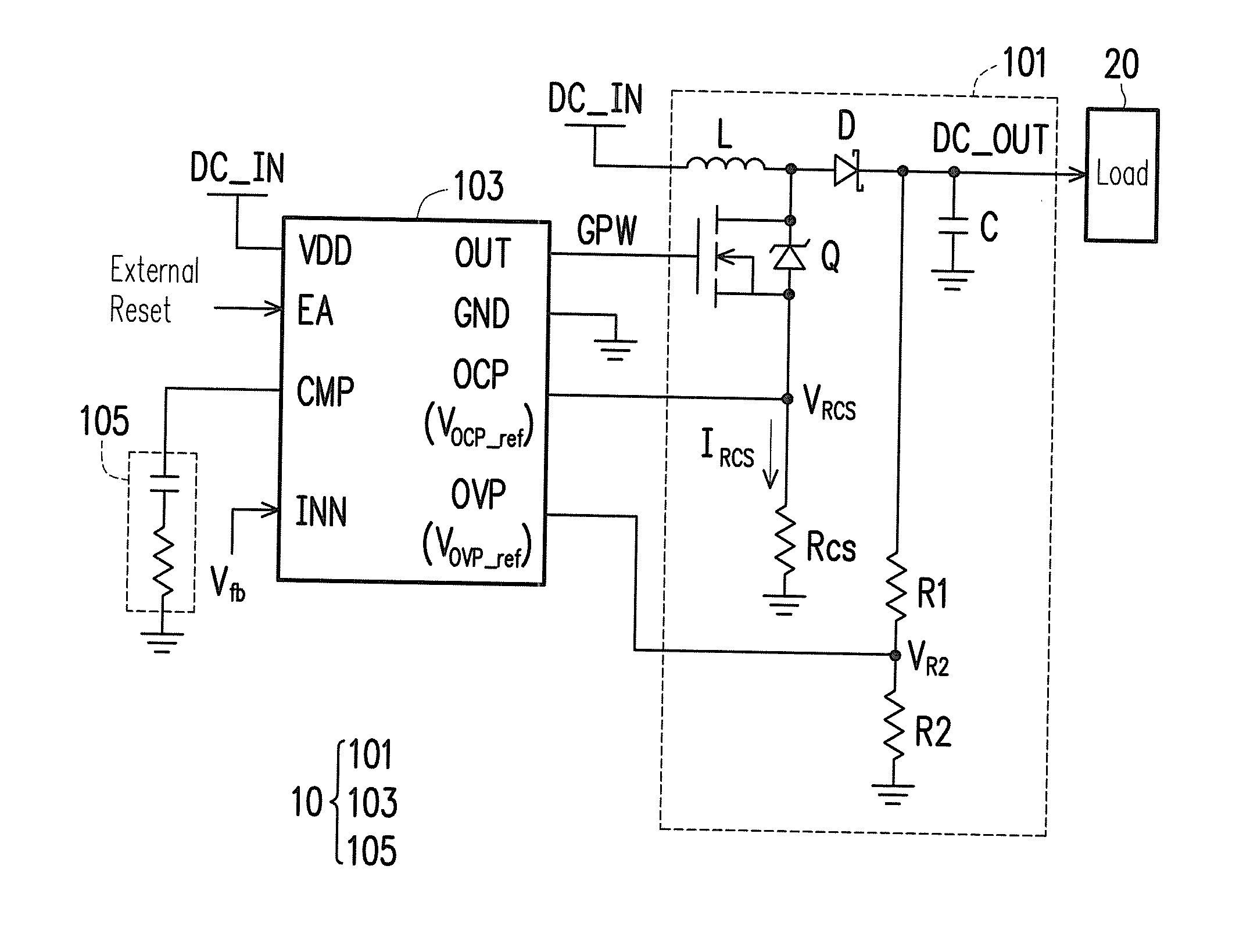
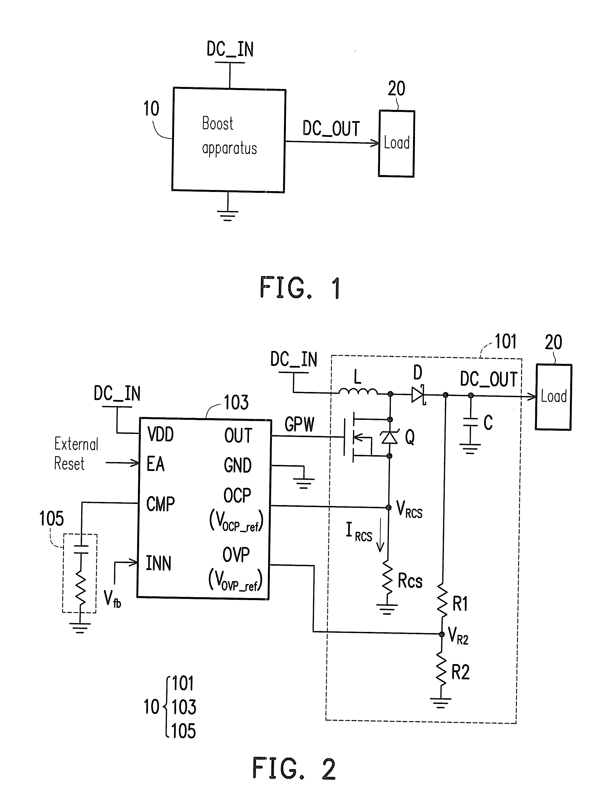
[0019]FIG. 1 is a block diagram illustrating a boost apparatus 10 according to an exemplary embodiment of the invention. FIG. 2 is a schematic diagram illustrating the boost apparatus 10 depicted in FIG. 1. With reference to FIG. 1 and FIG. 2, the boost apparatus 10 is adapted for providing a DC output voltage DC_OUT to a load 20 of any type. The boost apparatus 10 includes a boost power conversion circuit 101, a control chip 103, and a resistor-capacitor (RC) network 105.

[0020]In the exemplary embodiment, the boost power conversion circuit 101 may be configured to receive a DC input voltage DC_IN and provide the DC output voltage DC_OUT to the load 20 in response to a pulse-width-modulation (PWM) signal GPW that come...


PUM


Abstract

A boost apparatus adapted for providing a direct-current (DC) output voltage to a load is provided, and the boost apparatus includes a boost power conversion circuit and a control chip. The boost power conversion circuit has a diode coupled to the load. Besides, the boost power conversion circuit is configured to receive a DC input voltage and provide the DC output voltage to the load in response to a pulse-width-modulation (PWM) signal. The control chip is coupled to the boost power conversion circuit and configured to generate the PWM signal to control the operation of the boost power conversion circuit. The control chip is also configured to stop outputting the PWM signal and enter into a shutdown state when the diode is an open circuit or a short circuit, so as to protect the boost apparatus and / or the load from being damaged.

Description

CROSS-REFERENCE TO RELATED APPLICATION[0001]This application claims the priority benefit of Taiwan application serial no. 102129149, filed on Aug. 14, 2013. The entirety of the above-mentioned patent application is hereby incorporated by reference herein and made a part of this specification.BACKGROUND OF THE INVENTION[0002]1. Field of the Invention[0003]The invention relates to power conversion and supply technologies; more particularly, the invention relates to a boost apparatus capable of performing over-current and over-voltage protection functions.[0004]2. Description of Related Art[0005]Nowadays, a pulse-width-modulation based (PWM based) boost apparatus may be configured to provide a direct-current (DC) output voltage to a load. However, when the diode located on an output side (or at an output terminal) of the boost apparatus is an open circuit or a short circuit, the power switch located on the power conversion path of the boost apparatus may be damaged (e.g., encountering ...

Claims


Application Information

Patent Timeline
IPC IPC(8): H02M1/32H02M3/158
CPCH02M3/158H02M1/32H02M3/156
Inventor LIN, CHIU-YUANHUNG, CHIEN-PANGJUNG, KUANG-YU
Owner BEYOND INNOVATION TECH
Why Eureka
Try Eureka