Imaging system and imaging method

Active Publication Date: 2015-03-12
DAINIPPON SCREEN MTG CO LTD
View PDF6 Cites 6 Cited by
  • Summary
  • Abstract
  • Description
  • Claims
  • Application Information

AI Technical Summary

Benefits of technology

[0012]According to the present invention, the gradation correction processing is performed with the luminance values and the gradation values associated such that the luminance value corresponding to the luminance of the medium provides th

Problems solved by technology

In an imaging system of this type, a correlation between actual optical densities of imaging objects and gradation values obtained by expressing the optical densities by multi-gradation image data is not necessarily linear due to nonlinearity in the sensitivity of an, imaging system.
However, such a problem is naturally not considered in the above conventional technique aiming to read a document and only a correlation between luminance values and gradation va

Method used


Image

  • Imaging system and imaging method
  • Imaging system and imaging method
  • Imaging system and imaging method

Examples


Embodiment Construction

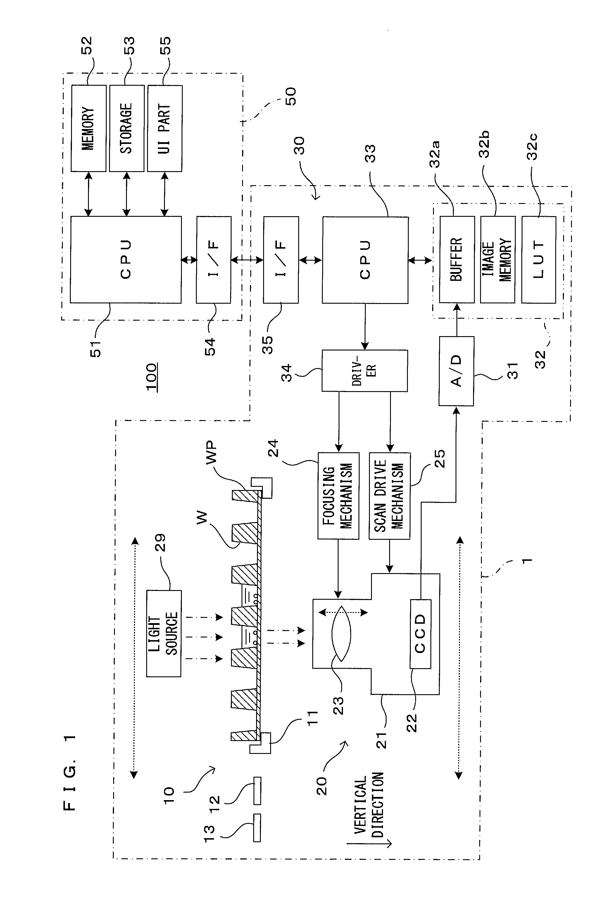
[0024]FIG. 1 is a view diagrammatically showing the configuration of one embodiment of an imaging system according to the invention. This imaging system 100 is a so-called line CCD scanner apparatus using a CCD line sensor as an imaging device and includes an imaging unit 1 with a sample holder part 10, an optical scanner part 20 and a control part 30, and a host computer 50.

[0025]The sample holder part 10 includes a holder 11 for holding a well plate WP substantially in a horizontal posture by being held in contact with a peripheral edge part of the lower surface of the well plate WP. Wells W for carrying a culture medium containing biological samples such as cells as imaging objects are formed on the upper surface of the well plate WP. Further, the sample holder part 10 includes a white reference plate 12 and an AF reference plate 13 to be read as references in a shading correction processing and an autofocus (AF) adjustment processing respectively to be described later.

[0026]The ...


PUM


Abstract

An imaging system 100 for imaging a sample in a medium carried in a container WP as an imaging object comprises: an imager 21 which obtains an original image by imaging the imaging object; and a data processor 33 which generates multi-gradation image data by performing a gradation correction on the original image, wherein the data processor 33 associates a luminance value corresponding to a luminance of the medium in the original image with a maximum gradation value in the gradation correction.

Description

CROSS REFERENCE TO RELATED APPLICATION[0001]The disclosure of Japanese Patent Application No. 2013-187116 filed on Sep. 10, 2013 including specification, drawings and claims is incorporated herein by reference in its entirety.BACKGROUND OF THE INVENTION[0002]1. Field of the Invention[0003]This invention relates to an imaging system and an imaging method for imaging a sample in a medium carried in a container as an imaging object.[0004]2. Description of the Related Art[0005]In medical and bio-scientific experiments, liquid or gel-like fluid (e.g. culture solution, medium or the like) is poured into each well of a plate-like tool (e.g. called microplate, microtiter plate or the like) in which a multitude of recesses also called as wells are, for example, arrayed, and things cultured herein such as cells are observed and measured as samples. In recent years, samples have been imaged and digitized by a CCD camera or the like and various image analysis techniques have been applied to ima...

Claims


Application Information

Patent Timeline
IPC IPC(8): H04N5/235G06T7/00
CPCG06T7/0012H04N5/2355G06T5/009G06T2207/30024G01N21/253G01N2021/1772H04N23/673H04N23/667H04N23/72H04N23/741H04N23/815G06T3/4053G06T2207/10024G01N2201/0621
Inventor IKEFUJI, KUNIOTSUMURA, JIRO
Owner DAINIPPON SCREEN MTG CO LTD
Why Eureka
Try Eureka