Power seat device

a technology of power seat and power seat, which is applied in the direction of movable seats, chairs, pulse techniques, etc., can solve the problems of difficult to mention that the operability of the operator is satisfactory, the operator cannot easily recognize the desirable direction of a certain lever, etc., and achieves convenient compressive deformation, prevent the deviation of the position of the operation unit, and improve the operability. satisfactory

Active Publication Date: 2015-04-23
SUMITOMO RIKO CO LTD
View PDF0 Cites 10 Cited by
  • Summary
  • Abstract
  • Description
  • Claims
  • Application Information

AI Technical Summary

Benefits of technology

[0017]Further, the operation unit may be fixed to the rear surface of the surface layer of the power seat body. Accordingly, even when the power seat body is deformed by the movement of the occupant, the positional deviation of the operation unit can be prevented. Accordingly, the operability can be satisfactorily improved. Further, when the operation unit is fixed to the rear surface of the surface layer, the dielectric layer can be easily compressively deformed by the operator's push operation. That is, the sensitivity of the operation unit can be satisfactorily improved.
[0018]Further, the control device may control the driving device so that the moving speed of the movable member increases with an increase in the capacitance detected by the detector. Here, a relation is established in which the capacitance increases with an increase in the push amount of the operator. That is, when the operator strongly pushes the operation unit, the moving speed of the movable member increases. This operation becomes an operation which is intuitively recognized by the operator. Accordingly, the operability is improved.
[0019]Further, the control device may compare the capacitance detected by the detector with each of the plurality of threshold values, and may control the driving device so that the moving speed of the movable member gradually increases with an increase in capacitance.
[0020]Here, even when the operator tries to apply a constant push force, the compressive deformation amount of the dielectric layer changes due to the movement of the movable member of the power seat body. Therefore, when the gradual threshold values are set and the moving speed of the movable member is gradually changed, a change in the compressive deformation amount of the dielectric layer with the movement of the movable member of the power seat body is not easily influenced. That is, the operator may not easily feel uncomfortable when the moving speed of the movable member of the power seat body changes.

Problems solved by technology

As in PL1 in which the power seat is operated by the operation lever provided at one position, an operator can not easily recognize a desirable direction of a certain lever.
In these power seats, it is difficult to mention that the operability of the operator is satisfactory.

Method used


Image

  • Power seat device
  • Power seat device
  • Power seat device

Examples


first embodiment

Description of Power Seat Body and Operation Unit

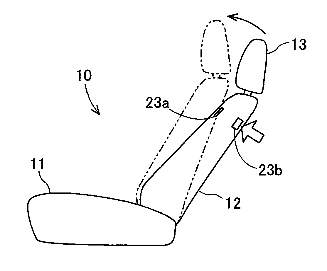
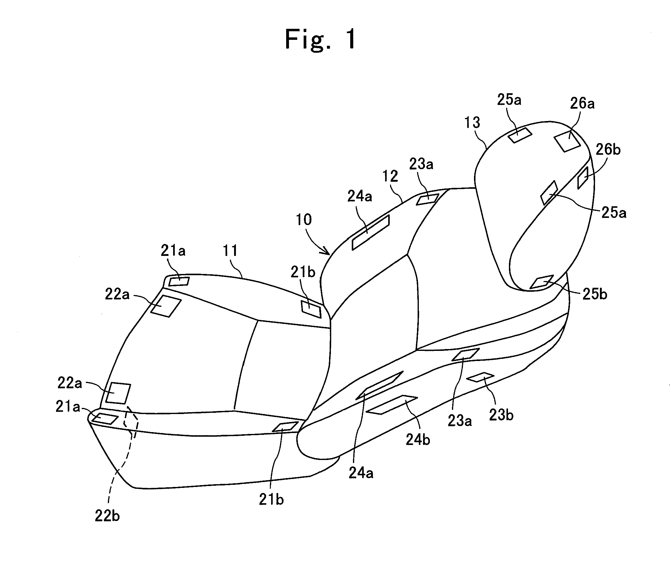
[0039]A power seat device of a first embodiment will be described with reference to the drawings. As illustrated in FIG. 1, the power seat device includes a power seat body 10 that can adjust a state (a posture). The power seat body 10 is applied to a vehicle seat, and includes a seating surface 11, a back surface 12, and a headrest 13. Further, the power seat body 10 can perform a longitudinal slide operation of the seating surface 11, a tilt operation of the seating surface 11, a reclining operation of the back surface 12, a forward and backward movement operations of a lumbar support (not illustrated) provided in the back surface 12, an upward and downward movement operations of the headrest 13, and an inclination operation of the headrest 13 through an electrical operation.

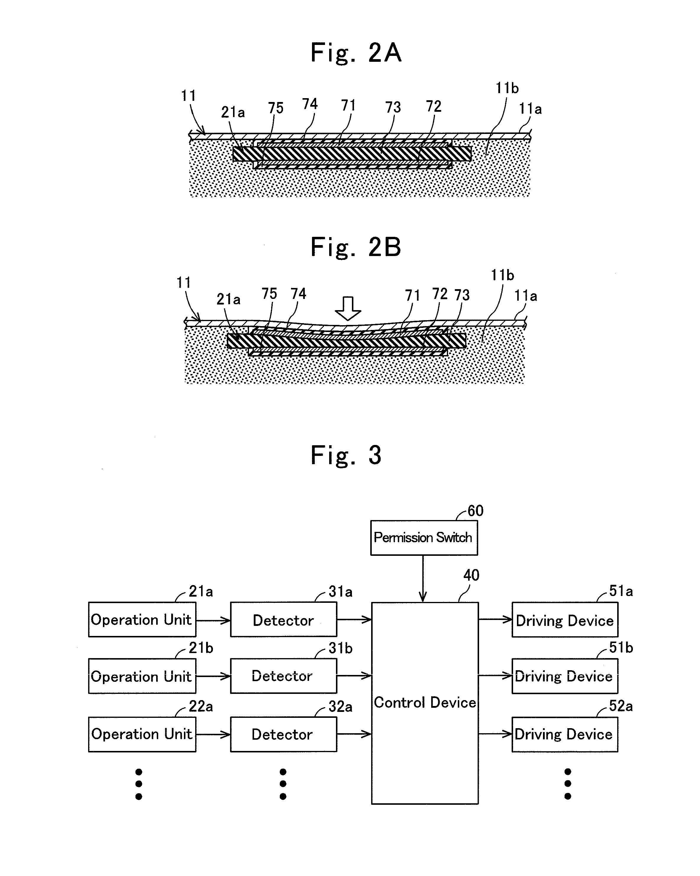
[0040]The power seat body 10 is provided with operation units 21a, 21b, 22a, 22b, 23a, 23b, 24a, 24b, 25a, 25b, 26a, and 26b for performing the operations of th...

second embodiment

[0081]In the above-described embodiment, as illustrated in FIG. 5, a relation is established in which the moving speed of each of the movable members 11 and the others linearly increases with respect to an increase in the detected capacitance change amount. In this embodiment, as illustrated in FIG. 7, a relation is established in which the moving speed of each of the movable members 11 and the others like gradually increases with an increase in the detected capacitance change amount.

[0082]The control device 40 compares the detected capacitance with each of a plurality of threshold values Cth1, Cth2, Cth3, and Cth4, and controls the driving devices 51a and the others so that the moving speed of each of the movable members 11 and the others gradually increases with an increase in capacitance change amount.

[0083]In this case, the capacitance detected by the detectors 31a and the others and the moving speed of each of the movable members 11 and the others will be described with referen...

third embodiment

[0087]In the above-described embodiment, the capacitance when the permission switch 60 becomes the permission state is set as the reference value. Alternatively, the reference value may be set as the capacitance when the capacitance change speed (the derivative value) is included in the set range. Hereinafter, this will be described by referring to FIG. 9.

[0088]The upper drawing of FIG. 9 indicates a behavior of the capacitance detected by the detector 31a with time as in the case of FIG. 6. The middle drawing of FIG. 9 indicates a behavior of the capacitance change amount per unit time (hereinafter, referred to as a capacitance change speed) with time.

[0089]The capacitance change speed (the derivative value) is higher than the upper-limit threshold value Cmax or is lower than the lower-limit threshold value Cmin when a human sits on the seat. Further, the capacitance change speed substantially becomes zero until the permission switch 60 becomes the permission state before and after...


PUM


Abstract

Provided is a power seat device in which an operator can intuitively recognize an operation of a movable member. Operation units are provided in movable members in a power seat body. Each of the operation units includes a pair of electrodes and a dielectric layer formed between the pair of electrodes so as to be compressively deformable, and compressively deforms the dielectric layer by an operator's push operation. Driving devices are controlled so that the movable members move in the push direction of the operator based on the capacitance between the pair of electrodes changing with the compressive deformation of the dielectric layer.

Description

CROSS-REFERENCE TO RELATED APPLICATION[0001]This is a continuation of Application PCT / JP2013 / 082115, filed on Nov. 29, 2013, which is incorporated herein by reference. The present invention is based on Japanese Patent Application No. 2012-261390, filed on Nov. 29, 2012, the entire contents of which are incorporated herein by reference.BACKGROUND OF THE INVENTION[0002]1. Field of the Invention[0003]The present invention relates to a power seat device.[0004]2. Description of the Related Art[0005]A patent literature 1 (PL1) discloses a power seat device that operates a movable portion of a power seat by an operation of an operation lever.[0006]A patent literature 2 (PL2) discloses a power seat device in which a sensor electrode is disposed in a backrest portion of a power seat and an inclination movement of the backrest portion or a forward and backward movement of a sitting portion is controlled by a change in capacitance between the sensor electrode and a hand or the like when an occ...

Claims


Application Information

Patent Timeline
Patent Type & Authority Applications(United States)
IPC IPC(8): B60N2/02H03K17/96B60N2/90
CPCH03K17/962B60N2/0228H03K2217/960755
Inventor YAMAMOTO, MASANORIHASEGAWA, KOUICHIHAYAKAWA, TOMONORI
Owner SUMITOMO RIKO CO LTD
Why Eureka
Try Eureka