Eureka AIR delivers breakthrough ideas for toughest innovation challenges, trusted by R&D personnel around the world.

Method and system for generating a ramping signal

Active Publication Date: 2015-06-18
CISTA SYST
View PDF10 Cites 4 Cited by
  • Summary
  • Abstract
  • Description
  • Claims
  • Application Information

AI Technical Summary

Benefits of technology

[0006]The present disclosure further provides a system for generating a ramping signal. The system includes a plurality of latches connected in series and configured to propagate a first enable signal based on a clock signal, and a plurality of first current generating circuits coupled to outputs of the latches. The first current generating circuits are configured to generate a first current signal based

Problems solved by technology

In operation, the quality of the ramping signal can significantly affect the quality of the output of the image sensor.
For example, a ramping signal with p

Method used


Image

  • Method and system for generating a ramping signal
  • Method and system for generating a ramping signal
  • Method and system for generating a ramping signal

Examples


Example

DETAILED DESCRIPTION OF THE DRAWINGS

[0018]Reference will now be made in detail to the exemplary embodiments consistent with the embodiments disclosed herein and the examples of which are illustrated in the accompanying drawings. Wherever possible, the same reference numbers will be used throughout the drawings to refer to the same or similar parts.

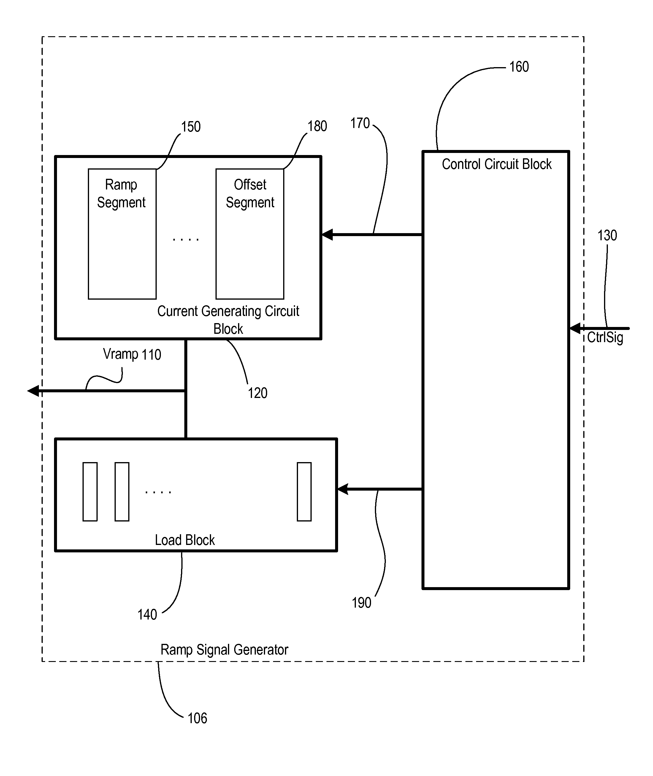
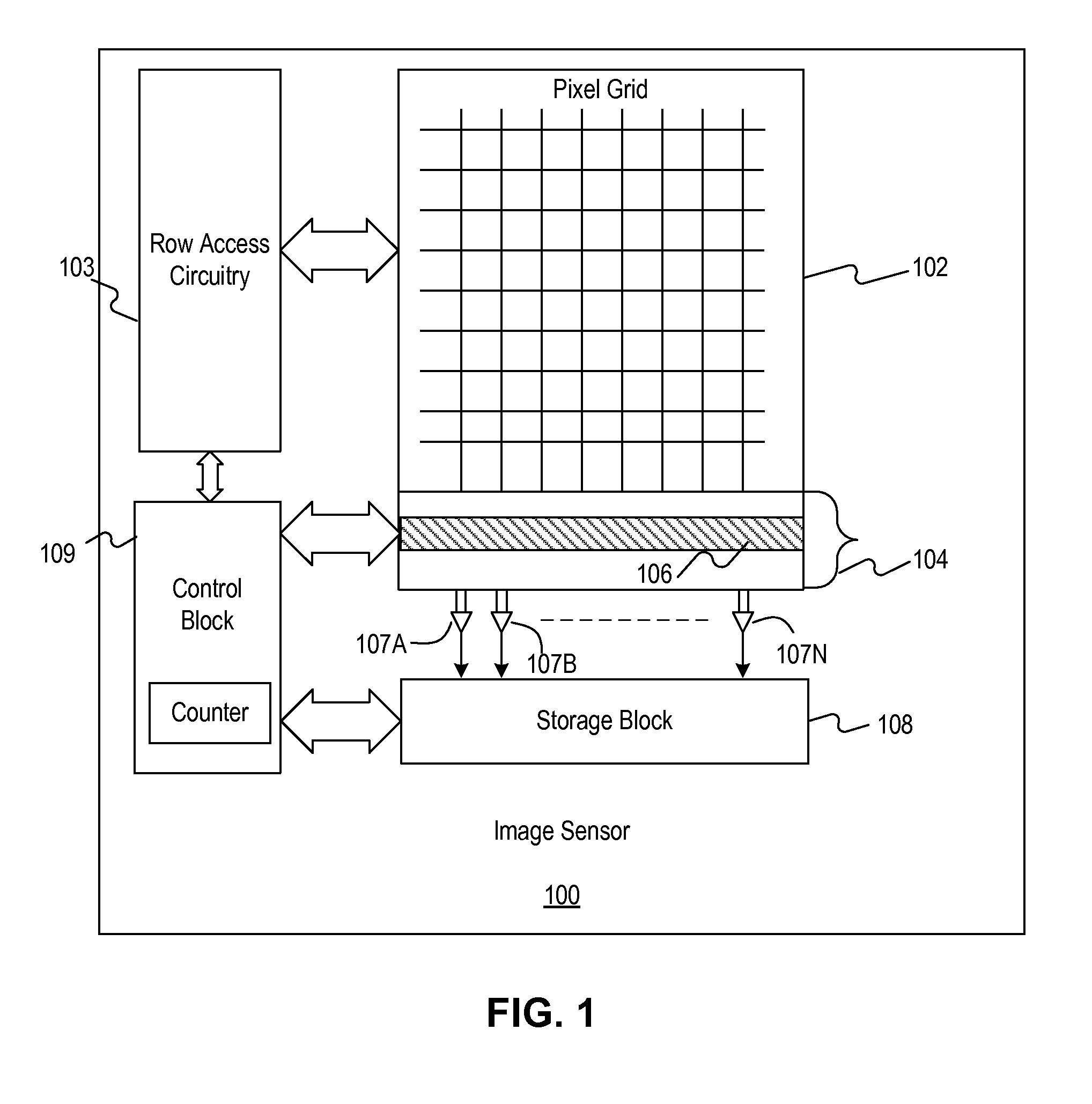
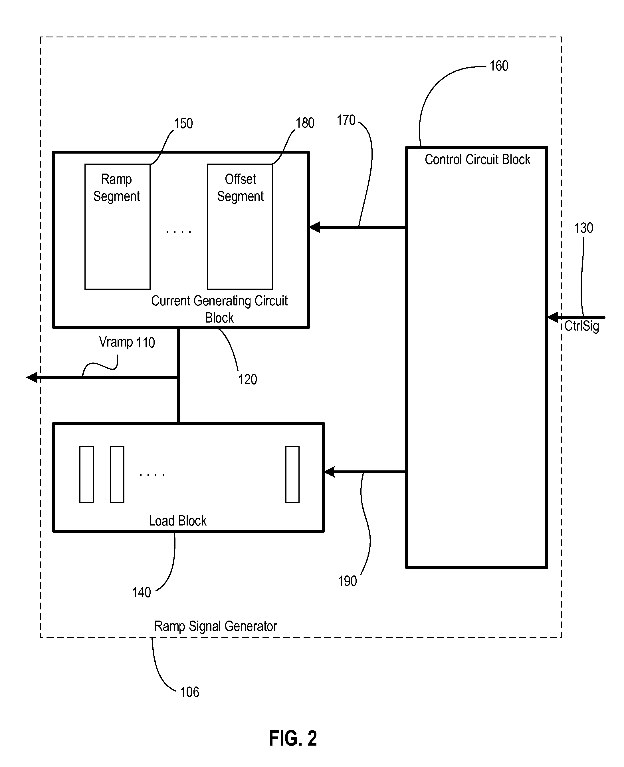
[0019]FIG. 1 is a diagram illustrating an exemplary image sensor 100. Image sensor 100 can be a CMOS type image sensor or a CCD type image sensor, or any other type of image sensors. Image sensor 100 may include a two-dimensional grid of pixels 102, row access circuitry 103, column access circuitry 104, a ramp signal generator 106, a series of comparators 107A-N, a storage block 108, and a control block 109. The image sensor circuitry is divided into blocks as shown in FIG. 1 for illustration purpose. A person having ordinary skill in the art should understand that at least some of these blocks can be integrated together on one chip.

[0020]...


PUM


Abstract

A system is provided for generating a ramping signal. The system includes a plurality of storage circuits each including an input and an output. The output of a previous storage circuit is connected to the input of a next storage circuit. The storage circuits are configured to propagate a first enable signal based on a first control signal. The system also includes a plurality of first current generating circuits. Each first current generating circuit is coupled to the output of a corresponding storage circuit to receive the propagated first enable signal. The first current generating circuits are configured to generate a first current signal based on the propagated first enable signal.

Description

CROSS REFERENCE TO RELATED APPLICATION[0001]This application claims the benefit of priority to U.S. Provisional Application No. 61 / 915,444, filed with the United States Patent and Trademark Office on Dec. 12, 2013, and entitled “A METHOD TO GENERATE A MONOTONIC RAMPING SIGNAL WITH LATCH PROPAGATED ENABLE SIGNAL,” which is hereby incorporated by reference in its entirety.TECHNICAL FIELD[0002]The present disclosure relates to methods and circuits for image sensing applications, in particular, to methods and circuits for generating a ramping signal as a reference signal for image sensor circuits.BACKGROUND INFORMATION[0003]Digital cameras, scanners, and other imaging devices often use image sensors, such as charge-coupled device (CCD) image sensors or complementary metal-oxide-semiconductor (CMOS) image sensors, to convert optical signals to electrical signals. An image sensor typically includes a grid of pixels, row access circuitry, column access circuitry, and a ramp signal generato...

Claims


Application Information

Patent Timeline
IPC IPC(8): H03K4/02H04N5/378
CPCH03K4/02H04N5/378H03K4/08H03K4/12H03K4/26H04N25/75H04N25/745H04N25/673H04N25/677H03K4/48
Inventor LEE, DENNIS TUNGLINZHANG, GUANGBIN
Owner CISTA SYST
Why Eureka
Eureka Blog
Learn More